Radio beacon
From HFUnderground
A radio beacon (Радиомаяк) is a transmitter at a known location, which transmits a continuous or periodic radio signal with limited information content (for example its identification or location), on a specified radio frequency. Occasionally the beacon function is combined with some other one-way transmission, like telemetry data or meteorological information.
Radio beacons have many applications, including air and sea navigation, propagation research, robotic mapping and radio frequency identification (RFID).
A very simple aviation radio navigational aid is the NDB or Non-directional Beacon. An NDB is simply a low frequency or medium frequency transmitter, which is used to locate airways intersections, airports or to conduct instrument approaches, with the use of a radio direction finder located on the aircraft. The aviation NDBs, especially the ones marking airways intersections, are gradually decommissioned, as they are replaced with other navigational aids based on newer technologies. Due to relatively low purchase, maintenance and calibration cost, they are still used to mark locations of smaller aerodromes and important helicopter landing sites.
There are also marine beacons, based on the same techonlogy and installed at coastal areas, for use by ships at sea.(1) Most of them, especially in the western world, are no longer in service, while some have been converted to telemetry transmitters for differential GPS. Chains of radio navigation Letter beacon for marine use are still active around the Russian and Ukrainian coastline.(2) (10)
NDB technical
NDBs typically operate in the frequency range from 190 kHz to 535 kHz (although they are allocated frequencies from 190 to 1750 kHz) and transmit a carrier modulated by either 400 or 1020 Hz. NDBs can also be colocated with DME stations, VOR beacon stations, and ILS marker beacons. NDB owners are mostly governmental agencies and airport authorities.
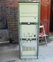
Transmission power varies. Locator beacons are low power, typically 25-100 W. Beacons marking airways are medium to high power, typically 200 W to 1 kW, and sometimes higher up to 5 kW. In most cases there are two transmitters at the beacon site, the main transmitter and a backup reserve transmitter. The backup transmitter sends the beacon identification morse code letters followed by a dot (morse code "E").
Antennas are of vertical polarization, either lattice towers with a "top hat" or T-like wire antennas supported between two masts. NDB antennas incorporate a segment that consists of an variable inductor or variometer and a variable capacitor in series, "tuned" to the particular frequency or frequencies assigned to that antenna. NDB's tuned segment is part of the antenna itself. There is often an electrical counterpoise, in the form of copper wires or wire mesh buried in the ground underneath the antenna.
Monitoring NDBs
Besides their use in aircraft navigation, aero NDBs and marine radio beacons are also popular with DXers. Because NDBs are generally low-power (usually 25 watts), they normally cannot be heard over long distances, but favorable conditions in the ionosphere can allow NDB signals to travel much farther than normal. Because of this, radio DXers interested in picking up distant signals enjoy listening to faraway NDBs. Also, since the band allocated to NDBs is free of broadcast stations and their associated interference, and because most NDBs do little more than transmit their Morse Code callsign, they are very easy to identify, making NDB monitoring a very entertaining niche within the DXing hobby.
In North America, the NDB band is from 190 to 435 kHz and from 510 to 530 kHz. In Europe, there is a longwave broadcasting band from 150 to 280 kHz, so the European NDB band is from 280 kHz to 530 kHz with a gap between 495 and 505 kHz because 500 kHz was the international maritime distress (emergency) frequency.
The beacons that are between 510 kHz and 530 kHz can sometimes be heard on AM radios that can tune below the beginning of the AM broadcast band. (For example, the "HEH" beacon in Newark, OH at 524 kHz is within the bandwidth of most AM radios, and the "OS" beacon in Columbus, OH at 515 kHz can also be heard on some AM radios). Some beacons can also be heard on 530 kHz, although from the adjacent frequencies such as "LYQ" at 529 kHz in Manchester, TN but for the most part, reception of NDBs requires a radio receiver that can receive frequencies below 530 kHz (the longwave band). Many so-called "shortwave" radios can receive all frequencies from 150 kHz to 30 MHz, which makes them ideal for listening to the stronger NDB signals. Whilst this type of receiver is adequate for reception of local beacons, specialized techniques (receiver preselectors, noise limiters and narrow IF filters) are required for the reception of very weak signals from remote beacons.(9)
The best time for NDB DXing is the last three hours before sunrise. Reception of NDBs is also usually best during the fall and winter because during the spring and summer, there is more atmospheric noise on the LF and MF bands.
ILS marker beacons
A marker beacon is a specialized beacon used in aviation in conjunction with an instrument landing system (ILS), to give pilots a means to determine distance to the runway. Marker beacons transmit upwards using beam antennas on the dedicated VHF mid band frequency of 75.0 MHz. ILS marker beacons are gradually phased-out and most new ILS installations have no marker beacons.
Radio propagation beacons
A radio propagation beacon is specifically used to study the propagation of radio signals. Nearly all of them are part of the amateur radio service.
Single letter HF beacons
See: Letter beacon
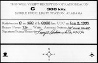
A group of mysterious radio beacons with single-letter identifiers ("C", "D", "M", "S", "P", etc) transmitting in morse code have been regularly reported on various HF frequencies. There is no official information available about these transmitters and they are not registered with the ITU. Some investigators suggest that some of these beacons (the so called "cluster beacons") are actually radio propagation beacons for naval use.
Space and satellite radio beacons
Beacons are also used in both geostationary and inclined orbit satellites. Almost every satellite transmits one or more beacon signals, normally on fixed frequencies. The satellite beacons are used to locate the satellite (determine its azimuth and elevation) in the sky and point the receiving antenna accurately. In addtion they contain modulated houskeeping information (telemetry). Many satellites transmit two distinct beacons, the general beacon, which transmits limited information in CW or FSK and is used for locating and identifying the satellite and the engineering beacon, which transmits telemetry data in FSK or PSK. Satellite radio beacons have proved useful in studies of various ionospheric phenomena, like traveling ionospheric disturbances, isolated plasma lenses etc.(11)
An S-band radio beacon was left on the moon by the Apollo 17 mission, transmitting FSK telemetry on 2276.0 MHz.(3)
Driftnet buoy radio beacons
See: Fishnet beacon, Not to be confused with fishnet stockings
Driftnet (or fishnet) radio buoys are extensively used by fishing boats operating in open seas and oceans.(4) They are useful for collecting long fishing lines or fishing nets, with the assistance of a radio direction finder. According to product information released by manufacturer Kato Electronics Co, Ltd., these buoys transmit on the medium frequency band 1600–2850 kHz (1.6 - 2.85 MHz) with a power of 4-15 W.
Some types of driftnet buoys, called "SelCall buoys", answer only when they are called by their own ships. Using this technique the buoy prevents nets and fishing gears from being carried away by other ships, while the battery power consumption remains low. Others transmit GPS location and/or other data via FSK (on the MF/HF band 1600 - 4000 kHz and the 11 meter 27MHz spectrum used by CB radio, the 25 MHz/26 MHz marine HF spectrum 25-30 MHz therefore act as telemetry transmitters and beacons. (5)
Per FCC regulations 47 CFR 80.376, radio buoy operations are authorized in the frequency band 1900 kHz - 2000 kHz. The use of the 1.9 MHz - 2.0 MHz frequency band for radiobuoy operations is limited to operations related to commercial fishing operations on the open sea and the Great Lakes. Transmitter power must not exceed 8 watts. Buoy antenna must not exceed 4.6 meters (15 feet) above sea level and ship-mounted antenna must not exceed a height of 6 meters (19 feet 9 inches) above the mast of the ship on which the antenna is installed.
Distress radiobeacons
Distress radiobeacons, also collectively known as distress beacons, emergency beacons, or simply, beacons, are those tracking transmitters that operate as part of the international Cospas-Sarsat Search and Rescue satellite system. When activated, these beacons send out a distress signal that, when detected by geostationary|non-geostationary satellites, can be located by triangulation. In the case of 406 MHz beacons which transmit digital signals, the beacons can be uniquely identified almost instantly (via GEOSAR). Furthermore, a GPS position can be encoded into the signal, thus providing both instantaneous identification & position. Distress signals from the beacons are homed by Search and Rescue (SAR) aircraft and ground search parties who can in turn come to the aid of the concerned boat, aircraft, and/or persons.
There are three kinds of distress radiobeacons:
- EPIRB (Emergency Position Indicating Radio Beacons) used for maritime distress,
- ELT (Emergency Locator Transmitters) signal aircraft distress
- PLB (Personal Locator Beacons) are for personal use and are intended to indicate a person in distress who is away from normal emergency response capabilities (i.e. 911)
The basic purpose of distress radiobeacons is to get people rescued within the the first 24 hours following an accident, when the majority of survivors can still be saved [1].
IEEE 802.11 Wi-Fi beacons
In the field of Wi-Fi (wireless local area networks using the IEEE 802.11b and 802.11g specification), the term beacon signifies a specific data transmission from the wireless access point (AP), which carries the SSID, the channel number and security protocols such as WEP (Wired Equivalent Protection) or WPA (Wi-Fi Protected Access).
A Wi-Fi beacon "frame" does not specify the link layer address of another Wi-Fi device, therefore it can be received and processed by any LAN client. (6)
- In infrastructure networks, beacon frames are sent by access points. Usually the beacon interval can be set though the access point configuration screen. An interval of 100 ms is recommended, as it provides good performance for most applications.
- In ad hoc networks there are no access points, so one of the peer stations assumes the responsibility for sending the beacon. After receiving a beacon frame, each station waits for the beacon interval and then, if no beacon is received, it transmits it's own beacon frame after a random time delay.
There are no special timeslot or channel reservations for beacons transmissions, so they are sent using the mandatory 802.11 CSMA/CA algorithm. If another station is sending a frame when the beacon is to be sent, then the access point must wait, therefore the actual time between beacon transmissions may be longer than the beacon interval. This is compensated by utilizing the timestamp found within the beacon frame.
Transmission of beacon frames generates a substantial amount of overhead. However, the beacon serves a variety of functions:
- Each beacon transmission identifies the presence of an access point. By default, each WiFi radio network interface (NIC) passively scans all RF channels and listens for beacons coming from access points in order to find a suitable access point.
- When a beacon is found, the radio NIC learns a great deal about that particular network. This enables a ranking of access points based on the received signal strength of the beacon, along with capability information regarding the network. The radio NIC can then associate with the most preferable access point.
- After association, the station continues to scan for other beacons in case the signal from the currently-associated access point become too weak to maintain communications. As the radio NIC receives beacons from the associated access point, the radio NIC updates its local clock to maintain timing synchronization with the access point and other stations. In addition, the radio NIC will abide by any other changes, such as data rate, that the frame body of the beacon indicates.
- The beacons also support stations implementing power saving mode. With infrastructure networks, the access point buffers frames destined for "sleeping" stations and announces which radio NICs have frames waiting for, through the TIM that's part of the beacon.
Most access points send beacons according to the standard. Some access points, however, suppress beacons for security reasons. Without a beacon, a station must know the SSID of the AP a priori. (13)
AX.25 packet radio beacons
Stations participating in packet radio networks based on the AX.25 link layer protocol also use beacon transmissions to identify themselves and broadcast brief information about operational status. The beacon transmissions use special UI or Unnumbered Information frames, which are not part of a connection and can be displayed by any station. (7) (8) Beacons in traditional AX.25 amateur radio, license free 11 meter band CB radio packet radio networks contain free format information text, readable by human operators. Other packet based beacon systems operate on licensed and unlicensed VHF and UHF radio services worldwide, including FRS, GMRS, MURS, Freenet and others.
This mode of AX.25 operation, using a formal machine-readable beacon text specification developed by Bob Bruninga, WB4APR, became the basis of the Automatic Packet Reporting System (APRS) networks.
AIS beacons
These beacons are VHF marine transmitters which send AIS (Automatic Identification System) packets. The packets contain spatial information spotting navigational hazards (reefs, skerries, shipwrecks etc) and navigational aids (buoys, ligts, racons). Thus AIS equipped ships can see the locations of navigation hazards on the AIS display.(12) Often the AIS beacon is not located at the indicated mavigation hazard spot but it is located at a convenient location on shore. An AIS beacon can send packets for more than one navigational hazards within its coverage area. This system is often called Synthetic AIS or Virtual AIS. These stations may also be programmed to provide other types of navigation safety information, for example, meteorological and hydrological data, via application specific text or binary messages (i.e. AIS messages 6, 8, 12, 14, or 25).
AIS information is transmitted on VHF marine channels 87B (161.975 MHz) and 88B (162.025 MHz) using 9600 bps Gaussian minimum shift keying (GMSK) modulation. AIS packets are formatted according to the HDLC (High-level Data Link Control) packet protocol. Shore based AIS beacons providing location and status of an aid to navigation (ATON) normally transmit AIS message 21 every three minutes.
- AIS 1 - 161.975 MHz
- AIS 2 - 162.025 MHz
- AIS 3 - 156.775 MHz
- AIS 4 - 156.825 MHz
See also
- Letter beacon
- High Frequency Beacon
- LowFER
- HiFER
- Radio propagation beacon
- 11 meter band beacons CB beacon 27 MHz beacons
References
- Appleyard, S.F., Linford, R.S. and Yarwood, P.J.: "Marine Electronic Navigation", 2nd edition, Routledge & Kegan Paul, ISBN 0-7102-1271-2, pp. 68–69, 1988.
- Connolly, R.: "Navigation Beacons", Radio & Communications Monitoring Monthly, 3(4), ISSN 1749-7809, p. 58, April 2008.
- Jessop, G.R., G6JP: "VHF-UHF manual" (4th ed), Radio Society of Great Britain, ISBN 0-900612-63-0, page 2.19, 1983.
- Pelagic Fishing Methods in the Pacific, Western Pacific Regional Fishery Management Council.
- Robert Connolly: "Greyline DXing, Fishing NDBs and NOTAM software", Radio User, 5(6), pp. 35–36, ISSN 1748-8117, June 2010.
- IEEE: "Local and metropolitan area networks — Specific requirements — Part 11: Wireless LAN Medium Access Control (MAC) and Physical Layer (PHY) specifications: Higher-Speed Physical Layer Extension in the 2.4 GHz Band (IEEE Std 802.11b-1999)", Institute of Electrical and Electronic Engineers, p. 2, 2003.
- AX.25 Link Access Protocol for Amateur Packet Radio
- Terry L. Fox, WB4JFI: "AX.25 Amateur Packet-Radio Link-Layer Protocol, Version 2.0", The American Radio Relay League, Newington, CT, ISBN 0-87259-011-9, p. 18, 1984.
- Remington, S., KH6SR: "On the Art of NDB DXing", The Longwave Club of America, 1987-1989
- Robert Connolly: "Time to get NDB hunting", Radio User, 6(6), pp. 5, ISSN 1748-8117, June 2011.
- Keneth Davies: "Ionospheric Radio", The Institution of Electrical Engineers, ISBN 0-86341-186-X, 1990, p. 296.
- U.S. Coast Guard: Types of Automatic Identification Systems, USCG Navigation Center, Alexandria, VA (2012).
- Bob Fleck, Bruce Potter: "802.11 Security", O'Reilly, ISBN 0-596-00290-4, December 2002.
Further reading
- Klawitter, G.: "Funk-Baken und Indikatorstationen" (in German), Siebel Verlag, ISBN 3-89632-055-6 (2001)
- NDB list website by Alan Gale, G4TMV
- Godfrey Manning: "Sky High: ADF and NDBs", Radio User, 2(12), pp. 25, ISSN 1748-8117, December 2007
- Godfrey Manning: "Sky High: NDB/ADF", Radio User, 3(1), PW Publishing Ltd, ISSN 1748-8117, pages=24–25, January 2008.
- The WiFi Alliance: WPA deployment for public access, 2004.
- Five steps to creating a Wireless Network
- Sheldon Remington, NI6E (ex KH6SR): "On the Art of NDB DXing", The Lowdown, 1987-1988.
| | This article contains textual material from Wikipedia (TM). Wikipedia texts are licensed under the Creative Commons Attribution-Share Alike license. In short: you are free to distribute and modify the text as long as you attribute its author(s) or licensor(s). If you alter, transform, or build upon this work, you may distribute the resulting work only under the same or similar license to this one. Wikipedia article: Electric_beacon | WP |
This site is a participant in the Amazon Services LLC Associates Program, an affiliate advertising program designed to provide a means for sites to earn advertising fees by advertising and linking to Amazon.com. Some links may be affiliate links. We may get paid if you buy something or take an action after clicking one of these.


