Category Archives: Transmitters

A simple and inexpensive frequency generator for homebrew transmitters, the Cypress CY22150

Virtually all homebrew transmitters are crystal controlled. This is excellent from a stability point of view, but creates the difficulty of having to obtain the crystals. Usually this involves hunting around hamfests and swapmeets, hoping you’ll find a crystal of a suitable frequency. This can be hit or miss, especially for “out of band” operation, like 43 meters, where it is more miss than hit.

I’ve done some experimentation with building my own Phase Locked Loop frequency generators, but the results were always dismal. I recently came across the CY22150 Programmable Clock Generator from Cypress. This single IC implements the PLL, divider circuits, and everything else. You just need a crystal for the reference (there’s a built in oscillator). And the crystal can be virtually any frequency.

First, you may wish to look at the CY22150 Datasheet

The CY22150 is in a TSSOP-16 SMD package, which is not very hobbyist friendly. I bought some of these adapters from eBay, which make the task of prototyping much easier. The CY22150 itself is available from Mouser and is $2.55 in single quantities.

The CY22150 uses an I2C serial interface to configure the various settings. For my experiments, I connected it to a Raspberry Pi single board computer. You could bit bang the I2C commands out the parallel port of a computer as well, if you wished. The CY22150 can also be programmed using Cypress supplied software, so no I2C interfacing is required. I have not tried this, but it could be useful in cases where operation on only one frequency is required.

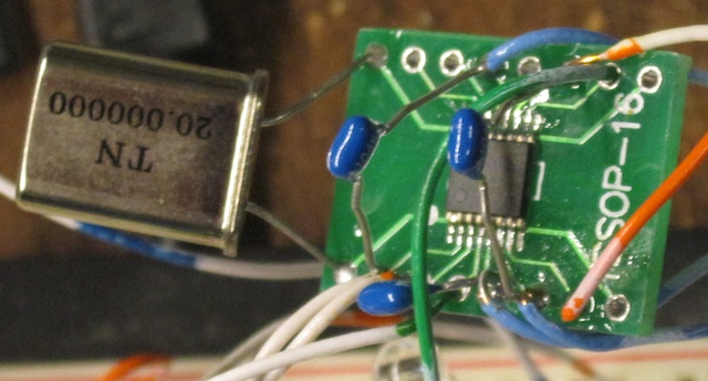
I soldered the CY22150 onto the PCB, and attached it to the Raspberry Pi, which also provided the 3.3 volt power:
Several registers in the CY22150 control the PLL, and set the output frequency. You have to compute three divider ratios. There are also several other settings, and I’ll go through them below:

First, after powering everything up, you need to enable one of the outputs. In my case, I am using Clock Output 1, so I need to set register 09H to a value of 01H.

Second, I need to specify the source of this output. The datasheet refers to this as the “Crosspoint switch matrix control”, and the end result is setting register 44H to 20H, which tells the chip that we want the output to be DIV1CLK divided by DIV1N.

Third, we need to set the chip to use the internal oscillator with a crystal. In my case, a 20 MHz crystal. We need to set the oscillator gain level, based on the crystal frequency. Referring to the datasheet, we need the gain bits to be 10, and the end result is register 12H is set to a value of 30H. I played around with these values, and did not find them to be critical.

Fourth, we need to set the input load capacitor control. These are equivalent to the small (10 pF or so) capacitors you connect to the crystal in an oscillator circuit. What nice here is that we don’t need any external capacitors, they are built into the chip, and we can select the values to use! Register 13H sets the capacitor value. And, we can adjust their value to move the oscillating frequency, so we can get it dead on. In my case, for a 20 MHz crystal, I needed to set register 13H to 8F.

Here is the 20 MHz oscillator output signal, looking at XOUT pin of the CY22150:
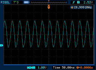
I finally get to use the screen capture mode of my Rigol scope!

Now it gets a little hairy. We need to compute the divider ratios. The datasheet shows you how to do this. I found some source code on the net that calculates the values for you, as an iterative process. There are multiple divider ratios to produce a given output frequency, the code finds the best set and smallest frequency error.

First, here is the C source code:


int main(int argc, char **argv)
{
double f_ref;
double f_out;

if (argc != 3)
{
fprintf(stderr, "usage: cy22150 refFreqkHz outFreqkHz\n");
exit(1);
}

f_ref = atof(argv[1]);
f_out = atof(argv[2]);

fprintf(stderr, "f_ref %g kHz\n",f_ref);
fprintf(stderr, "f_out %g kHz\n",f_out);

f_ref = 1000.0*f_ref;
f_out = 1000.0*f_out;

fprintf(stderr, "f_ref %g Hz\n",f_ref);
fprintf(stderr, "f_out %g Hz\n",f_out);

double q_min = 2;
double q_max = (int)(f_ref / 250000.0);
double d_min = (int)(1.0 + 100000000.0 / f_out);
double d_max = (int)(1.0 + 400000000.0 / f_out) - 1.0;
double f_test, f_diff;
double f_track = f_out;
double p_test, q_test, d_test;
int p, q, d;

for (q_test = q_min; q_test <= q_max; q_test++) { for (d_test = d_max; d_test >= d_min; d_test--)
{
p_test = (f_out / f_ref) * q_test * d_test;
p_test = ((p_test - (int)p_test) > .5) ? (int)(p_test + 1.0) : (int)p_test;
f_test = (f_ref * p_test) / (q_test * d_test);
f_diff = ((f_test - f_out) > 0.0) ? (f_test - f_out) : (f_out - f_test);
if (f_diff < f_track) { f_track = f_diff; p = (int)p_test; q = (int)q_test; d = (int)d_test; fprintf(stderr, "p:%d ",p); fprintf(stderr, "q:%d ",q); fprintf(stderr, "d:%d ",d); fprintf(stderr, "f_test:%g ",f_test*0.001); fprintf(stderr, "f_diff:%g \n",f_diff*0.001); } } } exit(0); }

Running it for 7175 kHz produces the following output:


$ ./cy22150 20000 7175
f_ref 20000 kHz
f_out 7175 kHz
f_ref 2e+07 Hz
f_out 7.175e+06 Hz
p:39 q:2 d:55 f_test:7090.91 f_diff:84.0909
p:39 q:2 d:54 f_test:7222.22 f_diff:47.2222
p:38 q:2 d:53 f_test:7169.81 f_diff:5.18868
p:33 q:2 d:46 f_test:7173.91 f_diff:1.08696
p:113 q:7 d:45 f_test:7174.6 f_diff:0.396825
p:221 q:14 d:44 f_test:7175.32 f_diff:0.324675
p:287 q:16 d:50 f_test:7175 f_diff:0

You call the program, passing it the frequency of your crystal, and the desired output frequency. It then goes through a few steps, and finds the best match.

The divider ratios are p, q, and d. In this case, they are 287, 16, and 50 respectively. These need to be set in several registers in the CY22150:

Ptotal (p) is the most confusing. We actually have to calculate what the datasheet refers to as PB and PO. The formula is P total = 2*(PB+4) + PO. In our case, we have 287=2*(PB+4) + PO. So PO is 1. Then we solve 286=2*(PB+4): 143=PB+4, or PB=139. That's 8BH.

PB goes into registers 40H and 41H. The high two bits go into 40H. You also need to write three charge pump control bits into 40H, and set the two high bits of 40H. In our case, the two high bits of PB are zero. So we just need to set the two high bits and the charge pump bits. From the datasheet, we want to write C4H. We also need to write the low bit into register 0CH when we set the D divider ratio, below. The 8BH value we calculated above goes into register 41H.

D goes into register 0CH. 50 decimal is 32 hex so we write 32H.

Q goes into register 42H. PO goes into the high bit. You actually have to write Q-2 into the register, so we need to write 14 decimal, which is 0EH. Plus since PO is 1, we set the high bit, so we end up writing 8EH.

Whew!

We ended up with these register settings:

09: 01 Enable output 1
0c: 32 D = 50
12: 20 Xtal drive
13: 8f Load capacitor set for accurate 20 mhz
40: c4 Set two high bits, bits 2,3,4 are charge pump, 4 is the correct value based on P
41: 8b PB=139
42: 8e Q of 16, so we set to 16-2=14, set high bit because PO (low bit) of P counter is 1
44: 20 Set the output to be DIV1CLK / DIV1N

For fun, you can also compute the divider ratios for say 6925 kHz:

p:277 q:16 d:50 f_test:6925 f_diff:0

Note that these values are based on a 20 MHz crystal. If you use a different value, they will be different. But that's the great thing about this chip, you can use whatever you have!

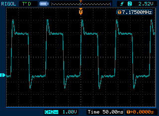
Here is the scope looking at the CLOCK 1 output :
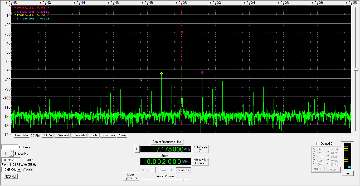
And here is what it looked like on an SDR-14:

As you can see, I do have a 60 Hz pickup issue to solve. No doubt due to the rats nest of wires. But... it works!

Since the Raspberry Pie may be overkill for many homebrew transmitter applications, another possibility, besides programming the Cy22150, would be to use a inexpensive microcontroller such as a PIC to send the I2C commands to the chip. I may look into this as a future project.

SAM_0110

Teaching LULU to Sing – AM Modulation


I hope you’ve had success with LULU so far.  If you are building for CW use, then you’re done.  However, this time around we will be a-modulating so we need to discuss some construction techniques before we start.    Most builders aren’t as anal about RFI prevention as I am when building rigs yet they rarely have problems.  I have experienced that too.  However, I have also spent many hours trying to hunt down the source of hum, or whine, or RF hash that is stubbornly haunting my project.   I have had rigs that worked fine for a time, then a bypass cap opens up… somewhere, and I’m off playing the feckless RFI hunter again.  My philosophy is this:  if you overbuild as you go along, the odds of having problems later on are greatly reduced.  In that spirit, I give you some RFI-fighting tips to consider as you lay out your chassis pan.  Best case would have the entire RF strip mounted inside a small metal box or RF shield inside the larger enclosure.  With LULU being so compact and cool running (Class E), a large enclosure is not needed.  And in this way, that sassy little hash generator is kept under wraps.  Second, any signal wire runs use shielded wire that is grounded on ONE end only.  Other long runs are wound through ferrites.  And third: redundant bypass caps are used at most input/output ports in the chassis.  Most of this is probably unnecessary, but I sleep better.  Maybe you will too.

SAM_0109


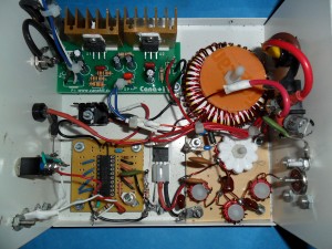
Purposely for this build I have IGNORED most of these “extras” as you can see in the photo.  I have kept the RF hammerlock in the modulated voltage line, the shielded audio input lead, and most of the bypassing caps – you should too – but I have left out everything else including all ferrites.  I have experienced no problems.  But this build was to illustrate this article and will rarely be used.  Any of my serious builds utilize all those tips I just gave you.  It’s your choice.


AUDIO AMPLIFIER

LULU Bridge Audio


In the past, little rigs in the 10 watt realm were modulated with a monolithic amp chip in a single-ended configuration.  Unfortunately, the typical LM383 or TDA2003 starts gasping for air before the modulator’s peak power needs are met.  Also, with a single-ended configuration, one side of the modulation transformer’s audio winding is grounded, which under some conditions can form a ground loop and cause a lot of hum.  The better way to modulate is to use a pair of TDA2003s in a bridged amp configuration.  This solves both problems.  The bridged pair circuit is shown above.


I have probably built half a dozen of these and they work well.  However, I have a better solution for you.  Cana Kit now features the bridged pair in kit form for 20 bucks plus shipping http://www.canakit.com/20w-bridged-audio-amplifier-kit-ck193-uk193.html.  That pre-made circuit board will save you a tremendous amount of time and cursing.  I will never build one of these from scratch again – ever.  Only you can determine what your time (and sanity) is worth.  A second option: Parts Express has a Bridgeable Class D Amplifier kit for 20 bucks that uses the Texas Instruments TPA3122.  I am just now experimenting with my first one of these.  I don’t know if it will survive as a modulator over the long haul.  Caveat Emptor…


MODULATION TRANSFORMER


Back in the day Boomer the Radio Animal rewound the venerable Radio Shack hash choke to use in his Grenades.  Unfortunately, they are no longer available.  Dave Martin uses a transformer pulled from a now defunct Taxi radio for his Commandos.  They aren’t available Stateside, and now sources in the UK seem to be drying up too.  Wind-able transformer iron in the small size range is tough to find.  You can find a lot of cores with interleaved E and I sections, but none with the separate parts like the old RS hash choke had.  There are a few websites that show how to separate interleaved cores.  I’ve tried it.  It’s about as do-able as shoving a wet noodle up a wildcat’s butt.  I decided to sidestep this whole issue and develop a toroidal transformer that would modulate well.  This is not a new idea.  However, most folks shy away from toroids because they are hard to wind, should you need a lot of windings as with a modulation transformer.  I’ll let you in on a little secret – they’re hard, but not THAT hard.


There are two downsides to using a toroid for this.  One: good luck trying to find a T200-26 core locally.  You’re gonna have to order one (or two?) from CWS Bytemark.  At this time they’re only about 3 bucks apiece.  You can stock up on your T50-2s and T80-2s on the same order.  Two: They take up a lot of space.  With the windings, it’s going to hog a footprint of 6 or 7 sq in.  The upside is that the audio is decent and the coupling is good enough to allow full modulation of LULU’s carrier signal.  Also, the #26 material has flat response across the entire audio range.


The “mod tranny” is basically an impedance matcher.  Your tranny’s winding ratio will depend upon how good a tweaker you were when building LULU’s RF strip.  If you feel unworthy because you could only get 8 or 10 watts out, then cheer up.  Your winding task will be much easier than that of the overachiever.  And you thought more was always better…


For up to 12 watts of RF output a 1:1 impedance ratio will work fine.  The amplifier has plenty of power capability to compensate for any mismatch.  Cut a couple of 7.5 foot lengths of 18 gauge magwire.  Secure one end of each in the chuck of a variable speed electric drill.  Secure the other pair of ends in a vise, or vice grips, or between your spouse’s teeth.  Using short bursts of the drill, spin them together until they have a couple of turns to the inch or so.  Then wind both windings at the same time.  Keep the turns tight to each other on the INSIDE of the core with no overlapping.  I was able to get 42 turns on the one in the photo.  Less stress…  Less pain in that arthritic wrist…


If you were able to tweak more output from LULU then you’ll need two separate windings.  And this one really IS a tedious transformer to wind.  Wrap the audio winding first.  You should fill the INSIDE of the toroid, keeping the turns tight with no overwinds.  If you use 18 gauge magwire you should be able to get about 80 turns on it.  A single layer of masking tape wrapped around the outside (like a belt) will help hold the windings in place.


To calculate the DC winding, first get a decent measure of your RF output BEFORE the harmonic filter (at the C9/L2 junction).  To find the approximate impedance at that point:


1)      Square the input voltage (12 * 12 = 144) and then divide the result by TWICE your measured power.  For example, if you measured your unfiltered output at 16 watts, your drain impedance would be approximately 144 / 32 = 4.5 ohms.


2)      The output impedance of the bridged audio amplifier is 8 ohms.  So the impedance ratio for our example would be: 4.5 / 8 = 0.5625.  Then take the square root of that result (0.75).  This is your required turns ratio.


3)      If you have an 80 turn audio winding, multiply that by the turns ratio (80 * 0.75 = 60).  You need 60 turns of wire overtop for your DC winding.  I should tell you to spread it evenly around the toroid.  However, it is mighty hard to do.  Just wind it as best you can WITHOUT OVERWINDS.  Admittedly this will take patience.  But hey, you only have to do it once…


PRE-PROCESSING


If you use LULU as is you will be a “wide Clyde”.  For AM communications work you must neck the audio down.  An outboard mic preamp or speech processor with a 3KHz audio cutoff filter is recommended.  For program content, the audio input is set up to receive a Walkman or MP3 player type output.  Pre-processing should be considered for increased readability of your signal.  Most audio software will do a good job.  Personally, I use Audacity to add compression and to roll off the highs above 8KHz with the EQ.  If you are a live kind of guy or gal, processing should be done at line level following your mixer.  A small line amp built from an LM 386 or similar can then boost the processed signal to LULU’s required drive level.  Good luck with this, have fun, and be safe out there!


Building the Basic LULU Transmitter


lulu-RF


I LOVE LULU


I have been happily turning mountains of electronic parts into scrap for nearly 50 years.  The quest for a well-performing, easy to build transmitter has greatly added to my slag heap.  After much pleasure and pain, I am pleased to present to you, Dear Reader, a transmitter that satisfies both criteria.  I offer you LULU…  Back around 2000, Norberto, an Argentine ham, put together several existing concepts and came up with the basic LULU design.   The LULU name is an affectation that came about in our builders group.  It is easier than calling it “an LU8EHA variant” as it was known for awhile.  We have made several changes to Norberto’s original design, but he would certainly still recognize it.


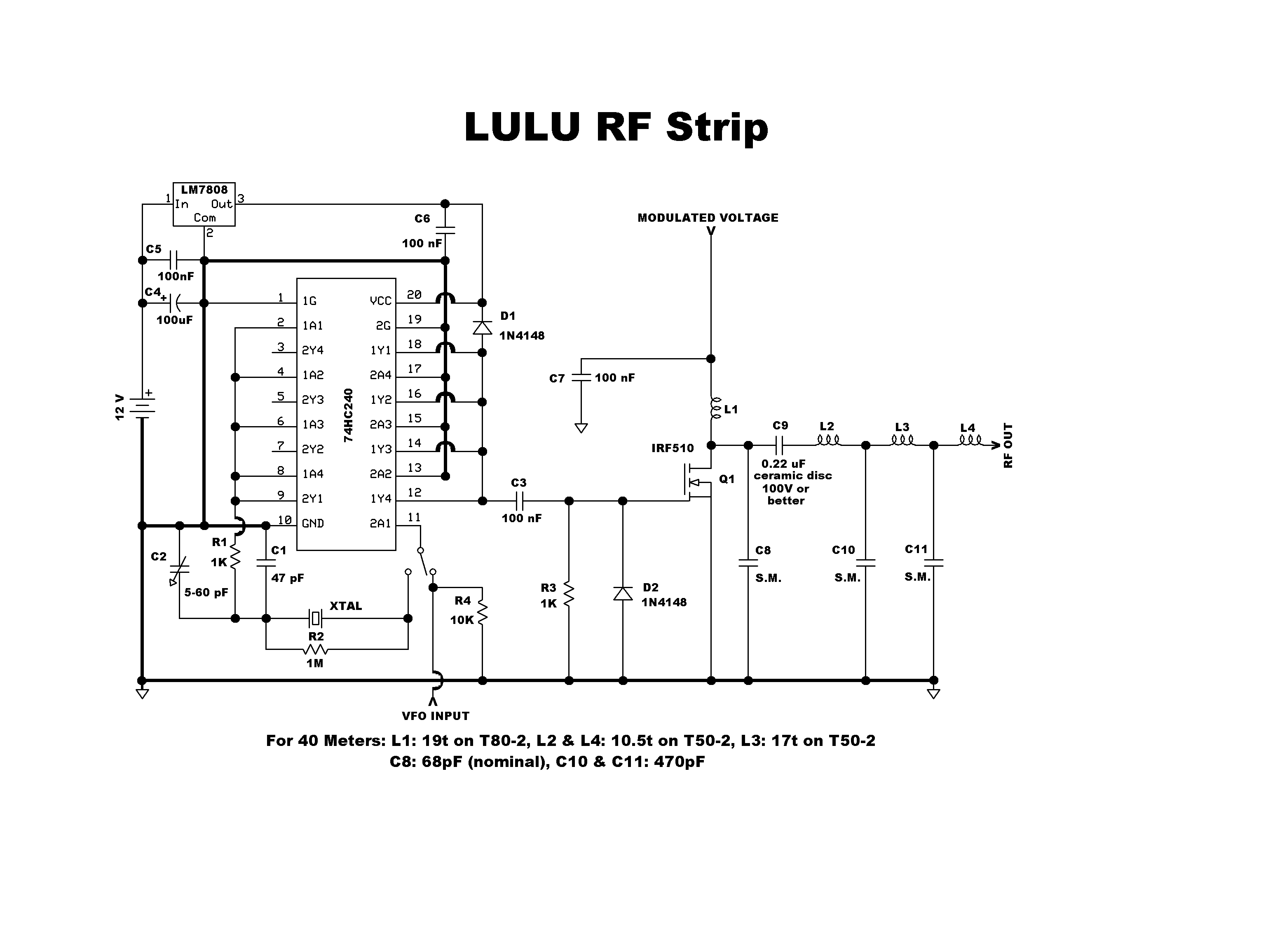
The heart of LULU is a 74HC240 octal buffer chip, which functions as an oscillator and driver.  Its gates are tied together to increase its ability to sink and source current.  Our active device is a MOSFET, which is turned on and off by swings of the input voltage.  We will be powering our buffer chip beyond its design limits, from an 8 volt regulator.  This begets a larger output voltage swing to the MOSFET than if we were playing by the manufacturer’s rules and powering the chip with 5 volts.  The chip acts as a digital driver, switching the MOSFET on and off, with the RF waveform being rendered in the drain circuit.  This digital method uses less parts, costs less, and generates less waste heat – advantage, LULU.


At a basic level of understanding, MOSFETS are electronic switches.  If a perfect switch is turned on, zero voltage appears across it and maximum current flows through it.  If turned off, maximum voltage (the supply voltage) appears across it and minimum (no) current flows through it.  Unfortunately, semiconductors aren’t perfect switches.  The voltage and current are always a bit out of phase, due to the MOSFET’s input and output capacitances which fight voltage changes.  These phase differences cause losses which manifest as heat.  Switch mode amplification has been developed to eliminate most of these losses.  LULU uses Class E amplifier topology to greatly enhance signal flow through the MOSFET.

LULU driver board

CONSTRUCTION


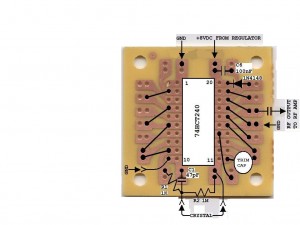
The Oscillator/Driver is the heart of LULU and you must have a properly functioning one before moving on.  I use the ubiquitous Radio Shack breakout board (RS 276-159B) method, as shown above.  The view is looking down on the components and jumpers side, but you “see” the copper tracing through the board, kinda like you were from the planet Krypton.   You can use either the HC or HCT family of 240 chips.  Keep in mind that we are running this chip very hard.  I use Mil Max SIP machined pin sockets because they allow air to flow underneath the chip, keeping it cooler.  This little dude will get quite warm.  I suggest that you use a VOM meter to chirp test all connections before plugging the 240 chip into the socket.  I usually find at least one continuity error every time I build this board.  When completed, power up and check for your signal with a nearby receiver set to your frequency.  If you find that the oscillator is sluggish, misfires, or won’t turn on at all, adjust trim cap C2.  If there’s still no joy, try soldering some extra capacitance across the trimmer.  You MUST have a well-functioning unit before moving on.  If you have an oscilloscope, you should see about 12-14 Volts p-p output at C3.  Be patient and do this one right.  Give LULU a good heart…

SAM_0108

Constructing LULU’s final is straightforward.  The given C8 value is nominal – it will get you into the ball park.  C6 is not sacrosanct.  Three 0.1uF (104) discs in parallel should work fine, but keep the value in the same zip code for best results.  All capacitors after the MOSFET drain (RF output and modulated supply circuits) must be at least 100V or better.  All resistors can be ¼ watt.  All coils are wound with #18 or 20 AWG.


TWEAKING


If you choose not to tweak, LULU will still work for you, but in Class C mode.  This means that your output power will probably be less and your final will certainly run hotter.  If you operate in this fashion, you MUST heat sink well.  A fan might also be needed.  Without tweaking, you should still see about 10 watts at the output.  However, to unlock LULU’s real potential, you’ll have to tweak.  The exact value of C8 will vary for differing IRF510s.  Keep in mind that in Class E operation, the class E point does not always correspond with max output.  Your efficiency tester will be your finger.  You should be able to comfortably keep it on the MOSFET – even for 5 minutes or more.  If you can’t, then keep tweaking.  I often use a Mica trimmer (5-100pF, 300V) in place of C8 and tune for max output.  Then finger test.  If it runs too hot, try tweaking the capacitance a bit in each direction.  You’ll eventually find a spot, near max output, that will also keep your finger happy.  Measure the trimmer’s capacitance and replace it with a fixed cap.  If you have a dual trace oscilloscope that will render well at 7 MHz, the MOSFET’s digital drive voltage at its gate will be “on” when its drain voltage is “off” and vice versa, more or less.  This shows the almost perfect switch in action – maximum current through it when it is on and maximum voltage across it when it is off.  IRF510s vary widely when used for RF.  I have always coaxed at least 16, and sometimes as much as 22 watts out of them in this circuit.


For CW operation:  Feed the modulated voltage input from the 12 volt supply and insert the key between pin 1 of the 240 chip and ground.  This will keep the oscillator gate running full time, while keying the driver gates on and off.


For VFO operation:  This input is included for frequency agility.  If you use an outboard frequency source, its output should be about 8Vp-p, to keep the 240 happy.  If unwanted, eliminate the switch and R4, and attach pin 11 directly to the crystal/R2 junction.


A switch mode transmitter like LULU is inherently narrow banded.   Operation should be limited to about 50 KHz either side of your tweaking frequency.


So build patiently and I hope you have some fun putting LULU together.  I will discuss AM operation in a later post… 73!