Just a test of the new server
Test Post
Leave a reply

Just a test of the new server
5436 kHz 3/10/16 1411 UTC (6:11am my time, sun is just up)
Now I just had to share this one. It was just higher in frequency than some radar stuff.
5436 kHz USB 3/28/2016 1449utc. I’ve got better reception today. Its either better propagation, or its because I’m not using my beverage this time which was aimed away from the Pacific.
Yessiree, I was going through my long Halloween SDR recording (notice its 1 1/2 months since then) and at the end of WPOD some neat stuff went on. I wanted to share it.
Hi, the other night I heard Old Time Radio fade in and I could actually understand a few phrases! This is the best I’ve heard it. However, I’ve only been listening for a few months over the Summer. It sounded like a Colgate ad for “tooth cream.” Cream sounds better than paste. Anyway, here’s a clip of my joy. You might need to turn up the volume and the patience because the fading is long. I captured it on my beverage aimed in the other coast’s general direction.
Old Time Radio 6770kHz, 0334utc 10/6/15
For the past several years, I have been hearing odd transmissions on 6914 kHz in AM mode. For lack of a better name, I’ve referred to this as the 6914 Oddity. I’ve heard a mix of cryptic voice transmissions, as well as MCW (morse code transmitted with an AM carrier) as well as RTTY and some MFSK digital mode, all transmitted in AM, not SSB as is typical with these modes.
The station will have a burst of activity, lasting for several days, then go silent for a period of time, weeks or even months.
Based on the times I can hear the station, and signal strengths, it seems to be something on the order of 500 to perhaps 1,000 miles from my location (Maryland). That could place it somewhere in the northern and eastern USA, or perhaps southern and eastern Canada.
I regularly run overnight and weekend SDR recordings from 6800 to 7000 kHz to catch any pirate stations that may be on, so these transmissions routinely show up in the recordings.
I observed the following voice transmissions last night (UTC 13 September 2015) on my regular overnight SDR recording:
0232 UTC
0259 UTC
0315 UTC
0331 UTC
0345 UTC
0401 UTC
0417 UTC
0429 UTC
0445 UTC
0500 UTC
0515 UTC
0529 UTC
At 1206 a transmission was made in an MFSK mode:
1206 UTC
This was followed at 1215 with an RTTY transmission. The signal was too weak to decode, but previously 50 baud and 1000 Hz shift was used, with a center frequency of 1700 Hz:
1215 UTC
There has been some speculation about the purpose of these transmissions. One thought is that they are SIGINT (signal intelligence) training exercises. But for now, the true purpose remains a mystery.
Yup, Liquid Radio’s little carrier wave usually fades in and out at my locale. Sometimes I’ll hear thumps but I’ve had to use USB demodulation in order to hear it. But last night I could hear music using AM demodulation and I wanted to share!
It helps to use big speakers when listening.
Liquid Radio, 6925AM, 0327utc, 5/2/2015
I have been very happy with the Resonant Loop which I have been using for the last couple of years; it has served me well, and will undoubtedly continue to do so in the future. It’s time to move forward, and push it’s capabilities a bit further. My current loop has a loaded Q of approximately 250 at 6925 kHz, and this results in a 3 dB bandwidth of around 28 kHz. This allows the tuning to be rather forgiving at the expense of being absolutely incapable of doing any significant frequency discrimination right within the antenna. To do so will require a loop with a higher Q, a significantly higher Q, and that will not happen using the technology of my current loop.
The loaded Q of a Resonant Loop is primarily determined by 3 things:
– The Q of the winding inductance. To get to the Q levels required, the best practical solution would be to wind the coil with a relatively large copper tubing; stranded wire is no longer practical here.
– The Q of the tuning capacitor. While the tuning diodes used in my current loop really make life easy, they just will not have enough Q at frequencies in the funny band. A high quality mechanical variable capacitor (or vacuum variable capacitor) will be required.
– The impedance presented by the buffer amplifier must be increased. The easiest way to do this is by using the loop windings as an impedance transformer to raise the effective input impedance of the amplifier.
After a lot of number crunching and simulations, I built the following prototype:
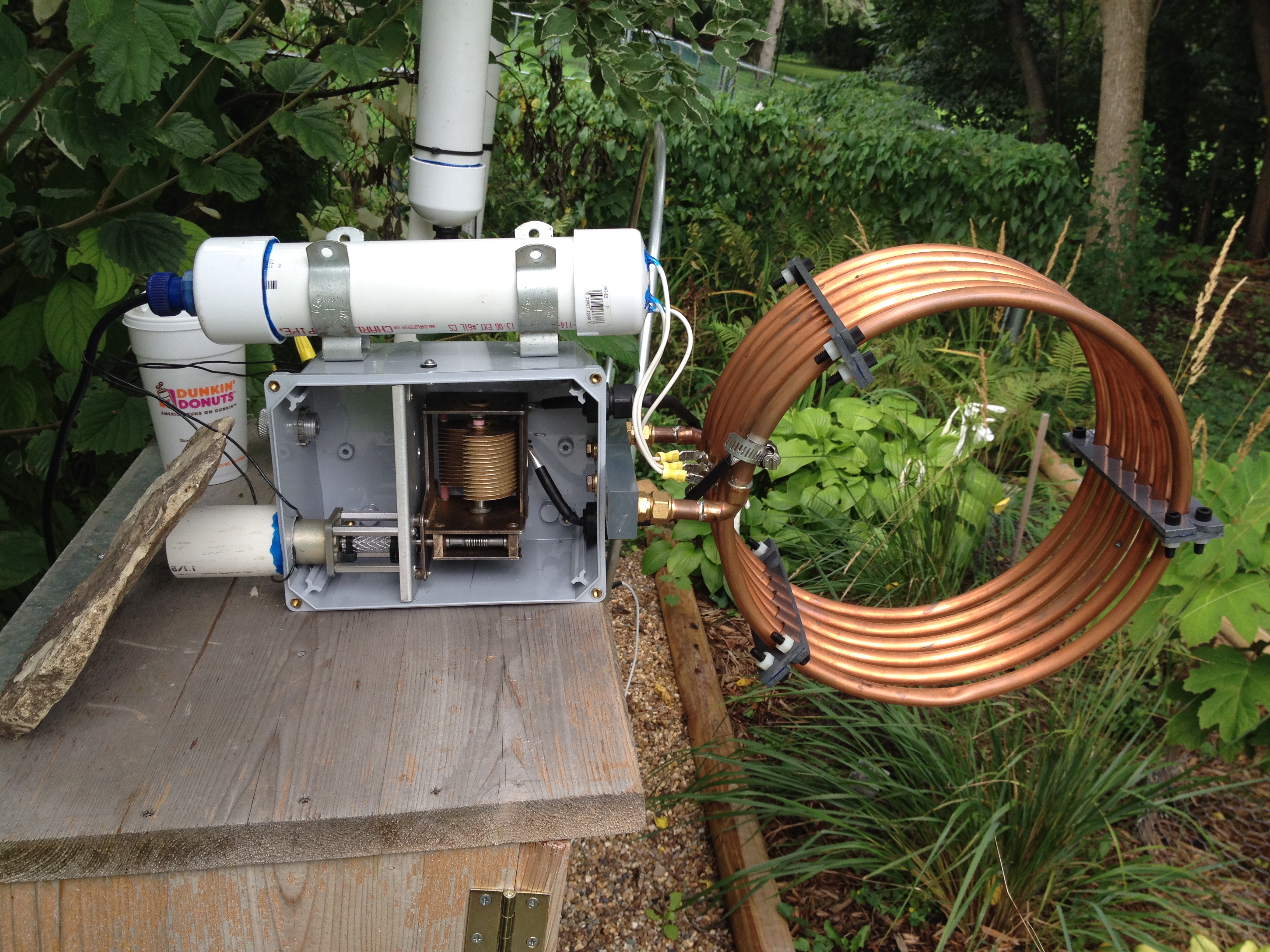
This is shown in a “testing position”, and a mast mount has not yet been built. A quick description of the loop follows.
The loop winding was built from 1/2″ OD soft copper refrigeration tubing, and was designed so that it could be fabricated from a 20′ length of tubing which is commonly available in DIY stores. The preliminary loop inductance is around 11 uH, and at 7000 kHz this winding should exhibit a Q of around 3000. The mean diameter is around 11.5″, and there are 6 turns with a 1″ spacing between turns. Note that copper sweat and brass compression fittings are used to create a solid loop mount to a bar of UHMW; these fittings are mechanical only, and are not part of the electrical circuit.
The capacitor used here is a purchase from Fair Radio Sales a number of years ago, and was a pull from a military ATU. As variable caps go, this is almost as good as it gets. The cap features solid brass construction, and is silver plated in entirety. All insulation is ceramic, and all plate joints appear to be silver soldered. The cap has a built-in 100:1 worm gear reducer with anti-backlash gearing. The measured capacitance range is 15-250 pF.
The windings and capacitor are connected by cobbled up flexible tubular pipes fabricated from some coax cable jacket over which was wound some 0.010″ pure silver foil which was held in place by heat shrink tubing. These pipes are soldered to the capacitor stator and rotor lugs. At the winding end, they are currently clamped onto the copper tubing with SS hose clamps (the clamping area was first silver plated with Cool Amp silver plating powder). At some point, these will be soldered.
Currently, the capacitor is remotely tuned by a PM DC gearmotor via a coupling made from a short length of PVC tubing and cable ties. The power supply is 3 D cells lined up in series against my logbook; I just touch the wire ends to the battery terminals and try to remember which way tunes up and which way tunes down? I have another deck built using an identical variable capacitor coupled to a 100 step/revolution stepping motor which will be used when the control circuits are built.
The white PVC tube above the chassis contains the loop buffer amp. This is just the standard JFET cascode amp used in most of my loops with the exception that the tuning diodes have been removed. A close-up of the hookup:
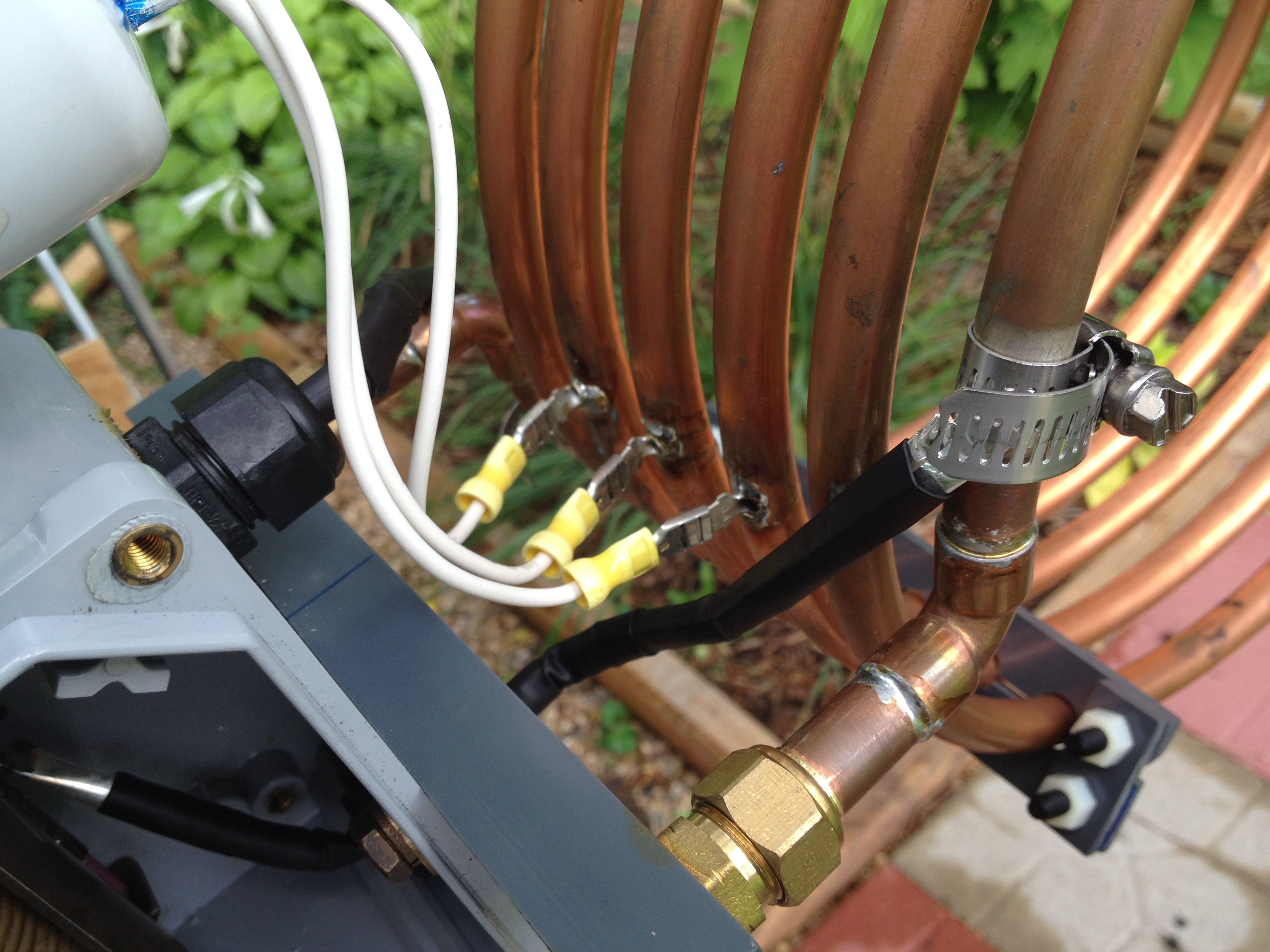
The loop tubing was drilled in 3 places to accept the barrels of male 1/4″ quick-connects, and these joints were then soldered. The loop amplifier is connected to these lugs. Note that this connection forms a 3:1 voltage transformer to the amp which results in a 9:1 amplifier input impedance transformation. The approximately 1 Meg amplifier input resistance now appears as a 9 Meg load on the capacitor-winding tank circuit which helps to keep the loaded Q high.
In starting this project, there were some known knowns. Primarily, I was pretty confident that a loop winding could be fabricated which would give me the proper inductance while at the same time giving me a required Q of around 3000. This build has proven that to me. There was also a major unknown known. It is extremely difficult to find hard data on the real Q of a mechanical variable capacitor of this type. The tubes are littered with vague statements which describe the Q of such caps as “very high”, “excellent”, and so forth. There are a couple of sites which have detailed Q information on a particular cap (which looked promising to me). But not this cap. Having built this loop, back calculations seem to suggest that the Q of this cap is somewhere around 1200-1500 at 6925 kHz, and this figure seems realistic to me.
My goal in this build was to raise the Q of a receiving loop by a factor of 2 or 3 from its current value of 250; I would be happy for a Q of 600. This would give an 3 dB BW of around 12 kHz at 6925; good, but not good enough to pry a pesc off of a pirate’s signal. So, what did we get?
To be honest, these results are preliminary, and vary all over the place. This is to be expected for such high Q circuits. The measurements can be tricky, and the results can be skewed by environmental things such as humidity, proximity to other objects, etc. At this point, Q measurements are consistently falling into a range between around 600 and 1050. I most commonly see values around 850 at 6925 kHz, and this thrills me to no end. A Q of 850 implies a 3 dB BW of around 8 kHz at 6925; if you squint, you can imagine that with a little more Q, some serious frequency discrimination can be accomplished.
How much more Q? I would LOVE to have a loop which exhibits a real 3 dB BW of 6 kHz at 6925; this would require a loaded loop Q of around 1150. At this point it is beginning to look realistic to me.
How do you get there with the current build configuration? One can calculate that at the current operating point (6925 kHz, Q = 850) that the LC tank circuit has a total effective series resistance of around 0.57 Ohms. I have gotten the greatest Q gains in the prototype by monkeying with the 2 connections between the winding and the capacitor, and I think that there is room for improvement there. Every milliohm counts. This particular capacitor also has the same Achilles heel that many variable caps have. the connection to the rotor. In this cap, there are 2 silver buttons on a spring loaded leaf, and these buttons wipe a silver commutation ring on the cap rotor. I have yet to do a really thorough cleaning of the sulphide layer on the ring, and have left this trump card in the back pocket. When I can no longer push the Q any higher, we will look here. There is also the possibility that this wiping contact can be replaced by a flexible silver tape, soldered to the ring.
There is a backup plan. This loop was built rigidly so that it would run in a stable manner at its tuned operating point. This would be a requirement for the next step, which would be to upgrade the loop to a so-called “regenerative loop” which could possibly supply some additional Q. More about this later.
In the few nights that I have used this for DXing, I have started to become familiar with the listening characteristics of this loop as compared to my standard loop. Although my current Neanderthal tuning supply makes it hard to peak the loop on a signal, the response peaks as seen on an SDR FFT plot are much more pronounced at Q=850 than they are at Q=250. With a 100 kHz view span, the 250 loop gives you a pretty good heads up look at a wide chunk of frequency spectrum; it’s hard to miss a weak signal off to the side of the loop response peak. Not so with the 850 loop; signals off to the side may be attenuated deeply, and it is quite possible to miss stuff.
On strong signal reception (say >= S7) it appears to be a coin toss between the 2 loops; both perform adequately. On weaker signals, I am giving the preliminary edge to the 850 loop. The 850 loop appears to be giving me better S/N ratio on weak signals, but I will hold this call until we are deeper into the season and storm noise lessens.
Which brings up another observation: when I had a wire antenna up, I noted that storm QRN as heard via the 250 loop was a lot “softer” than the crashes heard via a wire antenna. In the headphones, the storm noise was still there, but it tended to be less harsh and grating on the ears, and it was easier to “hear through” the noise on the 250 loop. I am noting now that storm QRN heard via the 850 loop is even mellower than that heard through the 250 loop. There is something going on there, as there is even a difference in lightning strike rendering in the SDR waterfall.
Well, enough for now.
A few months ago I got a shortwave radio with side band reception and a digital readout and it opened up a very interesting realm of the radio waves: the open waters that radio pirates hijack and sail upon. With their antennas raised high like the mast of a ship, they risk their butts to give you…a radio show!
I learned that some pirates make their own transmitters. And I found that its about the only way to transmit besides an official transmitter that is expensive. They also need to be kind of unlocked to use the pirate frequencies that are out of the legal transmitting band allocated to licenced ham operators. With my interests raised, another obsession began (I think I have a hobby of trying different hobbies. Its either this or I get obsessed easily.) The goal was to make a transmitter. So I found multiple plans for radios but the work required in learning electronics terminology and parts was too great. I use an interest-to-energy-required ratio. I knew nothing of electronics besides wiring up car stereos. “I dont know any of this and I don’t want to research a bunch of stuff because I’m too lazy. How do I know it will even work?”
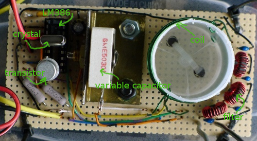
Then I found makerf.com that had plans for a simple transmitter. And its simplicity made the interest-to-energy-investment ratio favor the project. A friend had most of the parts laying around to make it: the LM386 integrated circuit, the 2222 transistor. What a coincidence, its my destiny! I just needed a crystal and a variable capacitor. I was also given a small bread board with wires. I am indebted to my generous friend!
First I made the LM386 audio amplifier to power a small speaker and it e-f-f-i-n-g worked! And I smelled something hot—the LM386. It felt HOT too. So the next day I learned from a coworker the electricity just flows as fast as it can unless you throttle it. It went through the LM386 too fast and made it dangerously hot. You can start a fire with this stuff. Electronics: manly toys. It flowed through the speaker too fast so I put resistors between the amp and the speaker and that slowed down the current and worked. I held everything together with 2 hands surprisingly. Just enough to make contact and see it work.
Then I made the transmitter. Its coil was ramshackle, made from the enamel coated wire of an old RC car motor. You just coil it around the correct number of turns on a form the correct diameter. And I ordered the 2 other vital parts, a crystal and a variable capacitor. And IT effing worked! Eff yeah! It made morse code beeps on the side band mode of my receiver! So 2 for 2.
Then I combined the amp and the transmitter and I had music coming out. Its easy to combine them, its just one wire from the amp to the transmitter! That makes sense! It was kind of low audio but it had promise. What if it worked better with all the parts soldered up with a pretty looking coil? So I ordered parts online. I made sure to buy the capacitors that the schematics recommended for the amp because I wanted good audio quality.
LM386 datasheet. An integrated circuit has a circuit of transistors and resistors inside of it, but at a microscopic level. This LM386 integrated circuit has a sheet that describes what it does. And I was able to generally understand it! It wasn’t all obfuscated with geek jargon. Its a product and they WANT people to be able to understand what it can do so they’ll buy it. This particular IC is worth producing because lots of people want a little amplifier for their projects. Look at the size of my metal can transistor. Its a little bigger than a pencil eraser. Can you imagine they fit transistors in there?
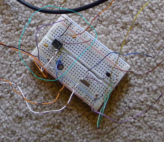
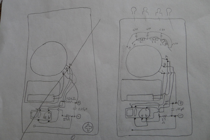
Then I drew out the wiring. I chose to use a socket for the transistor and crystal because I figured they might get hurt and need replacing. Its a good thing because they go bad later. I got the idea for a socket from a portable AM radio from the 60s. I wound the filter, its not that hard and kind of fun. The filter makes it so you transmit over a small area of the spectrum. Otherwise you will transmit all over the spectrum and you might transmit where somebody needs it like ambulance drivers and their dispatch. You can cause an ambulance driver to drive off a cliff without filters! Just kidding about the cliff. Winding is menial. I believe humans were created to do menial tasks like grooming, carving, and preparing food. Knitting is great! But I digress.

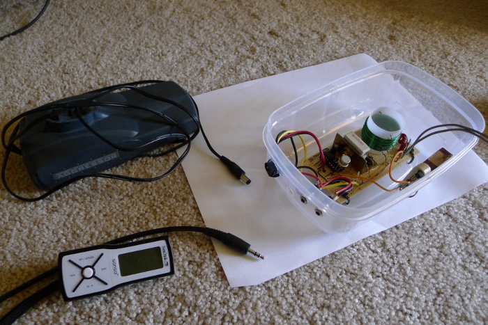
Lo and behold the official thing all soldered up. It looked great, just like makerf’s. But did it work? Yeah it did. I don’t remember being all “eff yeah” about this one. I think it was more “yeah, you better effing work.” I spent a lot of hours on this. About 2 full days worth of drawing, forming wire, and soldering. I adapted a 12v battery pack that plugs in to turn it on (unplug to turn it off). A switch and LED indicator light would be nice. The great thing about making it official was the ease of use. I didn’t have to hold everything together with tape and clothespins. I could turn it on and leave it now. My hands were free to turn the capacitor for tuning.
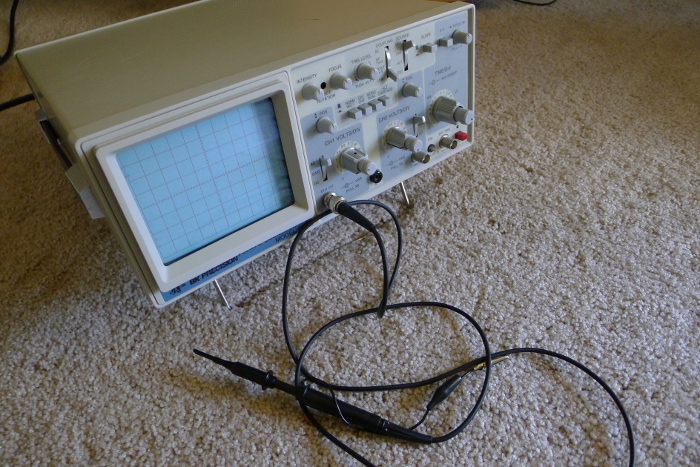
A friend loaned me an oscilloscope. The stuff you only see on TV. I was a bad-ass laboratory doctor now baby. I still want to use it in the garage with the door open and the screen facing out so the neighbors can see how much of a laboratory doctor I am….Turning the capacitor made a difference. The sine wave wasn’t very siney. I wish I made this when I was taking trigonometry. Prior, I found no use for trigonometry whatsoever. Good thing I took it twice so it stuck a bit more than the other useless crap. Too bad chemistry didn’t stick after taking it twice. Yes I’m bitter after obtaining a college degree and feeling the lack of good jobs available.
So I would “tune” it (twist the cap and watch the waves change). Nothing looked very “clean”. When I did this I also had the receiver on side band mode and the morse code beep would change tone as I adjust the cap. I don’t know what “clean” means for sure but I think it means a smooth wave with no sharp jagged points on it. Both the crystal and the transistor would get HOT sometimes. But it kept on working so I figured no harm done. Sometimes I didn’t have 50ohms worth of resistors between the antenna’s + and – output which is a no-no. Transmitting antennas have this same 50ohm property. I guess this throttles it, otherwise too much energy will go through the transistor and get it hot like it did my LM386? I don’t know. Use a non-conductor to twist the capacitor. I use a carved wooden stick. A metal screwdriver will change things when it gets near the transmitter. Just my finger will change the sound of the beep it makes as I move it around the transmitter. Pretty cool.
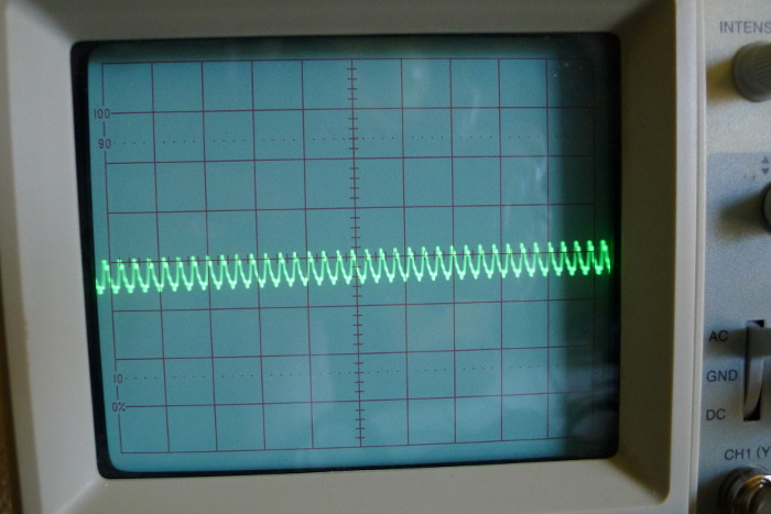
Here’s the first sine wave hooked up to ground and antenna out:
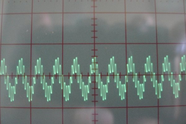
Here’s another with the oscilloscope probe touching the positive antenna out lead: (you can watch as a song with base really change the amplitude as the song plays)
Tuning observations: I twist it until it doesn’t work. Then I slowly twist the other way and a nice small sine wave shows up. The audio sound is weak. Then continue twisting slowly until it jumps and gets jagged and the sound is louder and fuzzy. A little more and the sound is as accurate as it gets. Any further and the treble is lost. And if it is overmodulated I turn down the volume on my audio device.
While turning the capacitor I accidently flicked the crystal and the transmitter stopped working. There’s an actual piece of a quartz crystal inside a container. Did you know that if you compress quartz it creates a small electrical current? The conspiracy theorists aren’t so crazy now are they. In reverse, if you add electric curent to a crystal it will vibrate. Oscillate is the way the laboratory doctors describe it. And depending on the thickness of the crystal it oscillates a certain number of times per minute. So 6.925mHz oscillates a different number of times per minute than 6.935mHz. Anyhow, thanks to the hfunderground forum members I learned that I probably needed a physically bigger crystal. Its called an FT-243 style and mine looks like its 100yrs old and was exumed by Indiana Jones from a cave. I had originally used a small crystal meant for computers. It would do well for morse code. But its not cut out for continual use apparently. Or being flicked while hot and oscillating.
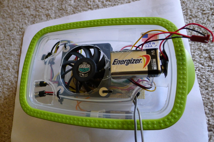
So it worked once again. Meanwhilst I installed a computer processor fan to the transmitter case to keep things cool. Otherwise transistor gets hot when the transmitter is on. The fan works great but if I wire up the fan to the transmitter power supply it makes a clicking sound in the received transmission! So I hooked up a 9v battery to the fan so it has its own separate power source for optimal fidelity.
Speaking of optimal fidelity, I didn’t like how the sound is pretty quiet compared to other stations. Its probably my coil because its not perfect. (I’m just joking, I think the coil doesn’t really have to be that perfect because my ramshackle coil worked ok). If I turn up the sound more than half way on my .mp3 player it gets all nasty sounding and its called overmodulating. You’ve heard it before. It kind of sounds like when you turn the volume up on a sound system past the point that your speakers can handle it and it gets distorted. But it happens when the volume is not very high. Well, my LM386 amp puts out a small 0.5Watts of power. So would it sound better if I had 0.75W? Well, I removed my LM386 and temporarily used a 20W amp in its place. I chose the left channel, put the black wire to ground and the red to the transmitter. Yup. But you see, I started with the volume all the way down and I slowly turned it up. But the sound was still low and nothing bad was happening so I turned it up more and then it started sounding pretty good but I smelled burning. And it stopped transmitting. And my 20W amp stopped too (it has built in protection and it still works). My transistor smelled like the culprit, but wasn’t that warm cause the fan was on it. Anyhow I was up an running with a spare I had just in case this happened. Good thing I put a socket on there. The thing is more powerful now! I think my original transistor got weakened from the heat I put it through so I’m glad I broke it and got it out of the way. However the sound is still quiet, it just transmits sound farther. Like out of the room…into the yard. Eff yeah! Then I plugged my computer sound output into the transmitter and it was louder! Not perfect but better than the .mp3. So after tests, .mp3 and discman are quieter than computer and laptop outputs. Hmmm.
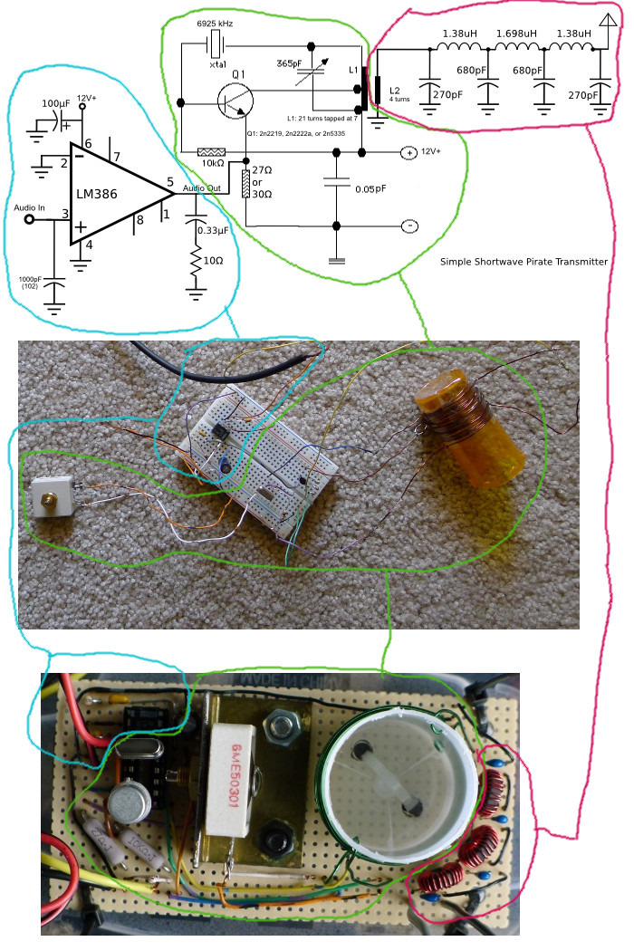
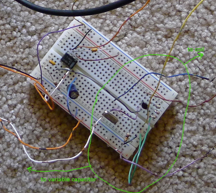
How the transmitter works. 3 parts:
Audio amplifier/modulator: The .mp3 player goes into the amplifier. This makes it strong enough to send to the transmitter.
The transmitter: works by magic. Seriously, I don’t know how it works. I know the recipe for it is on makerf.com . The crystal makes the frequency. The current changes direction in the coil really fast…I’m pretty sure…
Antenna: I know that the antenna works by induction. If you have electricity in the air, a wire will pick some of it up. So you have the coil with the oscillating energy with music data added to it. Wrap a wire around the coil and it will pick up the power. Put the filter between this and the antenna. Send it on its way through the filter and out to your transmitting antenna, into the atmosphere where it bounces off of special layers of ions back to the Earth a hundred and more miles away. I heard Border Hunter radio the other day and they are in Europe! You know he uses one of these babies…not really. His has more magic.
If its working and then quits, I think the only variables that break are the LM386, the crystal, and the transistor. Or heat has melted the solder between joints. My interest grew as I made this. This growing interest fuels itself so I am willing to expend more energy into working on it. Its even more important than my internet addiction. I’m talking about general time wasting on the internet that just wastes the time. Really, how important is a blow dart gun video? (note to self: google how to increase night vision) Now I have an actual book about antennas that I’m actually reading. I can’t transmit without a good antenna otherwise I might burn out a transistor. Wow, I just realized I can put that notch in my belt. There are those that have blown transistors and then there’s everybody else. I plan to get a ham radio license and test this baby out on the air. If anything, the morse code will transmit farther than the audio. I learned morse code from an iPhone app. Use the internet for good, not for time wasting blow dart gun videos.
From start to finish my project took me 4 months and I have a part time job and an internet addiction to fight.
I will share the total price (shipping included):
small crystal $19
magnet wire $16
audio jack $6
radio parts from mouser $19
toriods and antenna jacks (not used yet) $15
more transistors $8.50 (shipping was about $6)
big crystal $12.50
crystal socket $13
Total: $109 (Dr. Phil’s audience gasps and whispers)
This doesn’t include perf board $6 and LM386 a couple dollars. And the effing time and energy I put into it $200 (more gasps)
It was worth it! ![]() I am proud of it. 8)
I am proud of it. 8)
UPDATE June, 2014
Well, with my newly acquired ham license, I finally tried my transmitter with 2 antennas: an adjustable inverted V and an inverted L with a ground radial. I tried both antennas through an antenna tuner. As well as the inverted V without a tuner (because it was resonant on the frequency I wanted and therefore theoretically had a good impedance and thus no need for a tuner). Well, it hardly transmitted out of my yard.
I think the reason could be:
-that my circuit wires are too long (they rout down to the socket with the transistor and back up)
-that my coil could be tuned better
So if I were to invest the time and effort to make this go farther I would first try to shorten the circuit wires (solder the transistor directly and don’t use the socket). And second, find out the resonance of my coil. I think a noise bridge could be used for this but I’m not sure.
UPDATE UPDATE: January, 2015
Some fine electronics sages at HFU have some improvements on the design! To make it louder, give it more power. I was using the LM386 N1 which is weaker than the LM386 N3. Wimpy wimpy wimmmmpy.
So, this wise man’s advice to make better: “my gut tells me to place a very large value capacitor (250 uf or greater) in the line between the audio chip and the oscillator and put a resistor of say 16 ohms from the audio chips output to ground. The Capacitor will pass the audio but will keep any DC current from entering the audio chip. The chip might (I say might) not like having DC entering the output of the audio chip.
If I were to try this circuit I would use a 380 chip and not the 386 as shown.”
There you have it, sage advice. Literally. Thanks!
My thoughts: Hmmm, this sounds like it would fix the weak audio because if you amplify the audio on my stereo speaker system, they get louder.
Caught this 3/8/14
While waiting for ANTI Milano to sign on at 1457z 15515kHz, this popped up out of nowhere – NOT caught in progress:
African american male “Morning”? Then mentions of “the metropolis of San Francisco, CA”, “Macon County Alabama”, “Macon County Executive Committee”, “Alabama National Democratic Party”, “Last 3 presidential elections”, “isn’t it strange”, “27 years ago”. Then ANTI Milano.
Any one have a clue?
Besides counting pirate radio listening as one of my huge wastes of time, I spend a lot of hours and money driving my land barge pickup truck around to yard sales. Generally speaking, 98% of yard sales have nothing of interest to me; trinkets and children’s clothes and toys and broken Chinese power tools. But every now and again, I find something interesting. So yesterday morning, I park me truck on an impossibly narrow street and trudge the rest of the way on foot up to a small yard sale, where at the foot of the driveway, I immediately see this: 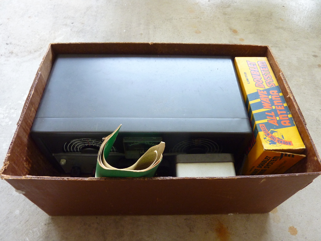
“It’s a ham radio!” exclaims the middle aged guy running the sale. “How much?” I ask. “$20″. I bargain on everything. So my counteroffer of $15 was accepted. And off I go to hump the box back to the truck much to the puzzled consternation of Mrs. Beerus.
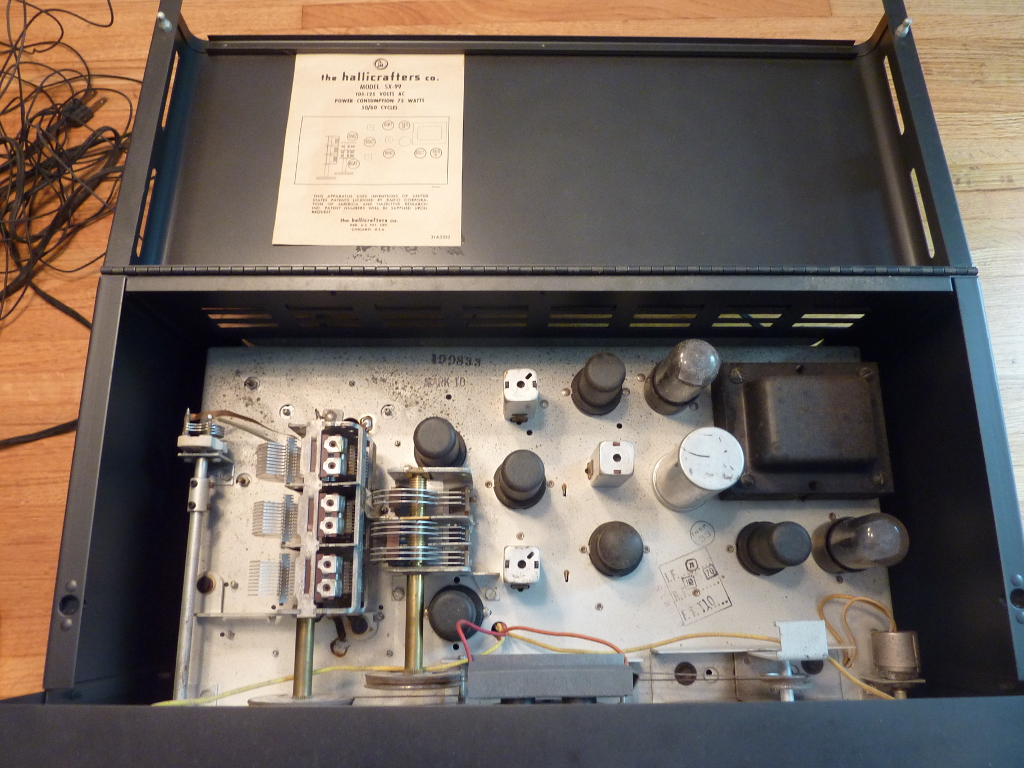
So, what’s in the box? Well, it’s a pretty mint Hallicrafters SX-99, with a speaker, and a doublet antenna still in the box.
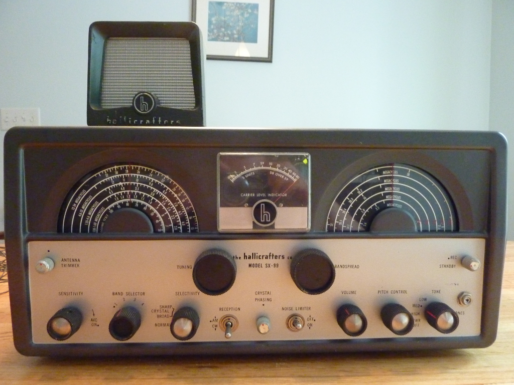
You might notice the silver knob inserts missing from several knobs; I have those, and just need to glue them back in. They fell out when I took the radio out of the box.
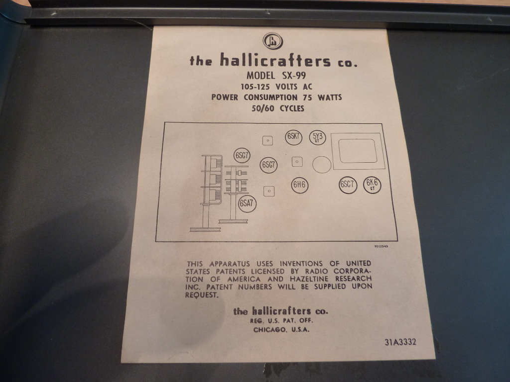
The inside of the radio is complete, and very clean!
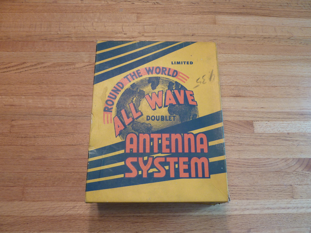
This antenna box has some 1950’s panache.
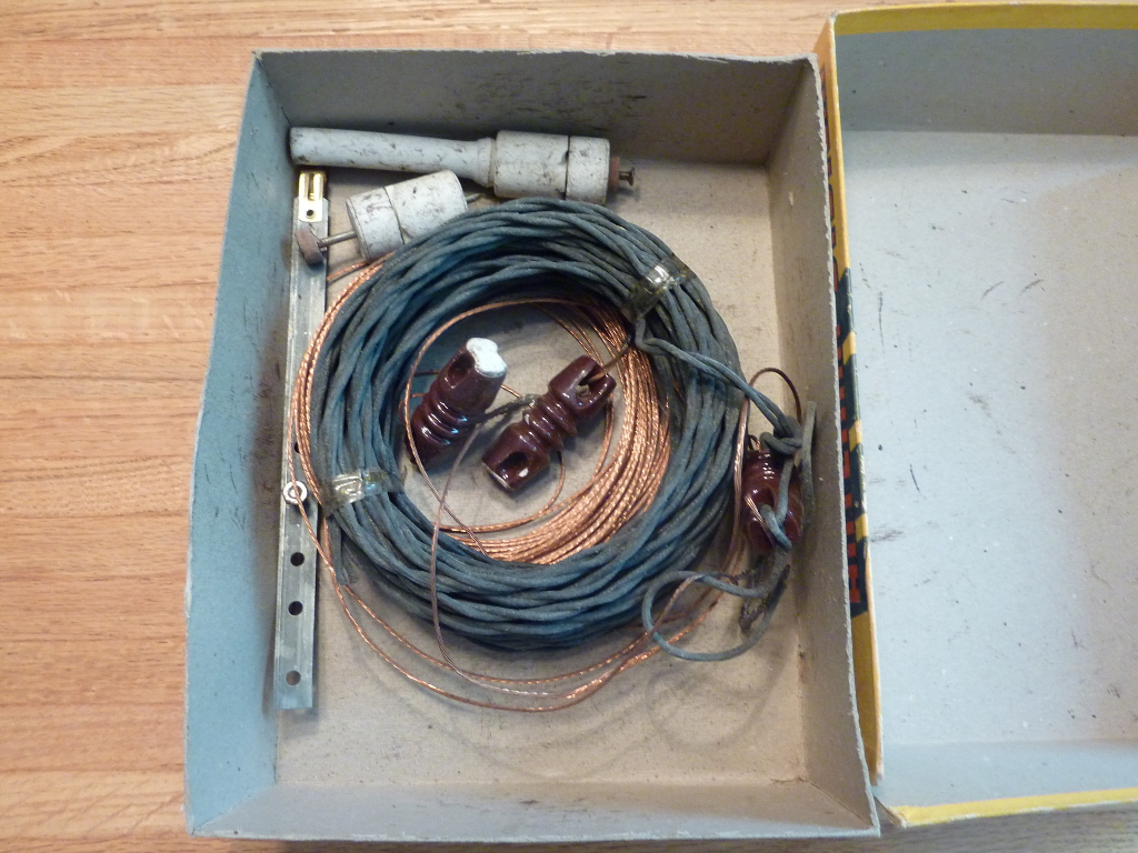
The antenna copper itself has no tarnish and the twisted pair feedline is still taped up like it was from the factory so I don’t think this antenna was ever hung.
So that’s it, my friends. My yard sale find for August 3rd, 2013. I showed you it. I have other things I have found over the years that may be future blog posts. As well, I will post anything new I come across. What have you found? You can post about YOUR yard sale finds over at the HFU! Check out this thread:
http://www.hfunderground.com/board/index.php/topic,12018.0.html
Cheers for now!