
I have been very happy with the Resonant Loop which I have been using for the last couple of years; it has served me well, and will undoubtedly continue to do so in the future. It’s time to move forward, and push it’s capabilities a bit further. My current loop has a loaded Q of approximately 250 at 6925 kHz, and this results in a 3 dB bandwidth of around 28 kHz. This allows the tuning to be rather forgiving at the expense of being absolutely incapable of doing any significant frequency discrimination right within the antenna. To do so will require a loop with a higher Q, a significantly higher Q, and that will not happen using the technology of my current loop.
The loaded Q of a Resonant Loop is primarily determined by 3 things:
– The Q of the winding inductance. To get to the Q levels required, the best practical solution would be to wind the coil with a relatively large copper tubing; stranded wire is no longer practical here.
– The Q of the tuning capacitor. While the tuning diodes used in my current loop really make life easy, they just will not have enough Q at frequencies in the funny band. A high quality mechanical variable capacitor (or vacuum variable capacitor) will be required.
– The impedance presented by the buffer amplifier must be increased. The easiest way to do this is by using the loop windings as an impedance transformer to raise the effective input impedance of the amplifier.
After a lot of number crunching and simulations, I built the following prototype:
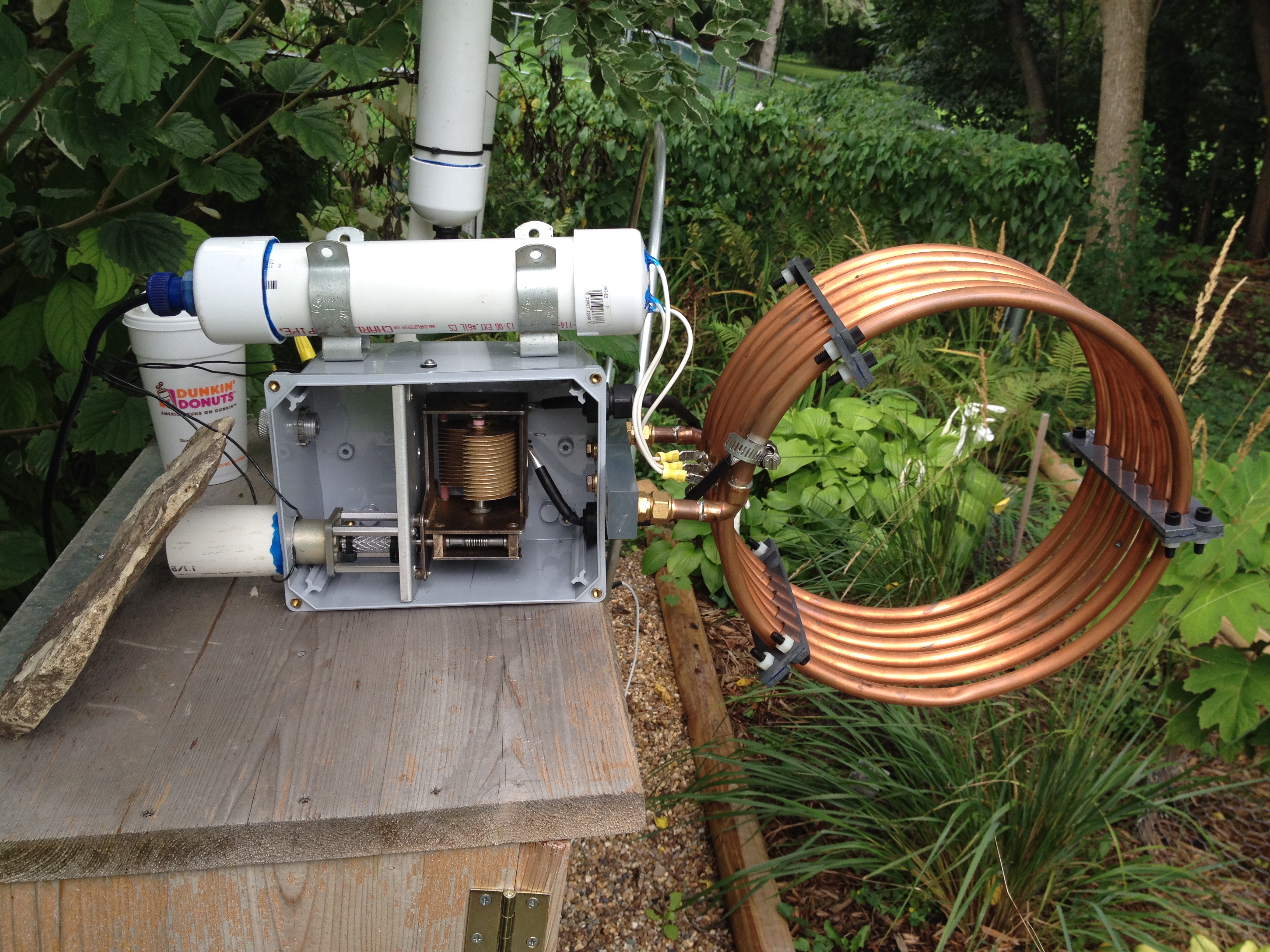
This is shown in a “testing position”, and a mast mount has not yet been built. A quick description of the loop follows.
The loop winding was built from 1/2″ OD soft copper refrigeration tubing, and was designed so that it could be fabricated from a 20′ length of tubing which is commonly available in DIY stores. The preliminary loop inductance is around 11 uH, and at 7000 kHz this winding should exhibit a Q of around 3000. The mean diameter is around 11.5″, and there are 6 turns with a 1″ spacing between turns. Note that copper sweat and brass compression fittings are used to create a solid loop mount to a bar of UHMW; these fittings are mechanical only, and are not part of the electrical circuit.
The capacitor used here is a purchase from Fair Radio Sales a number of years ago, and was a pull from a military ATU. As variable caps go, this is almost as good as it gets. The cap features solid brass construction, and is silver plated in entirety. All insulation is ceramic, and all plate joints appear to be silver soldered. The cap has a built-in 100:1 worm gear reducer with anti-backlash gearing. The measured capacitance range is 15-250 pF.
The windings and capacitor are connected by cobbled up flexible tubular pipes fabricated from some coax cable jacket over which was wound some 0.010″ pure silver foil which was held in place by heat shrink tubing. These pipes are soldered to the capacitor stator and rotor lugs. At the winding end, they are currently clamped onto the copper tubing with SS hose clamps (the clamping area was first silver plated with Cool Amp silver plating powder). At some point, these will be soldered.
Currently, the capacitor is remotely tuned by a PM DC gearmotor via a coupling made from a short length of PVC tubing and cable ties. The power supply is 3 D cells lined up in series against my logbook; I just touch the wire ends to the battery terminals and try to remember which way tunes up and which way tunes down? I have another deck built using an identical variable capacitor coupled to a 100 step/revolution stepping motor which will be used when the control circuits are built.
The white PVC tube above the chassis contains the loop buffer amp. This is just the standard JFET cascode amp used in most of my loops with the exception that the tuning diodes have been removed. A close-up of the hookup:
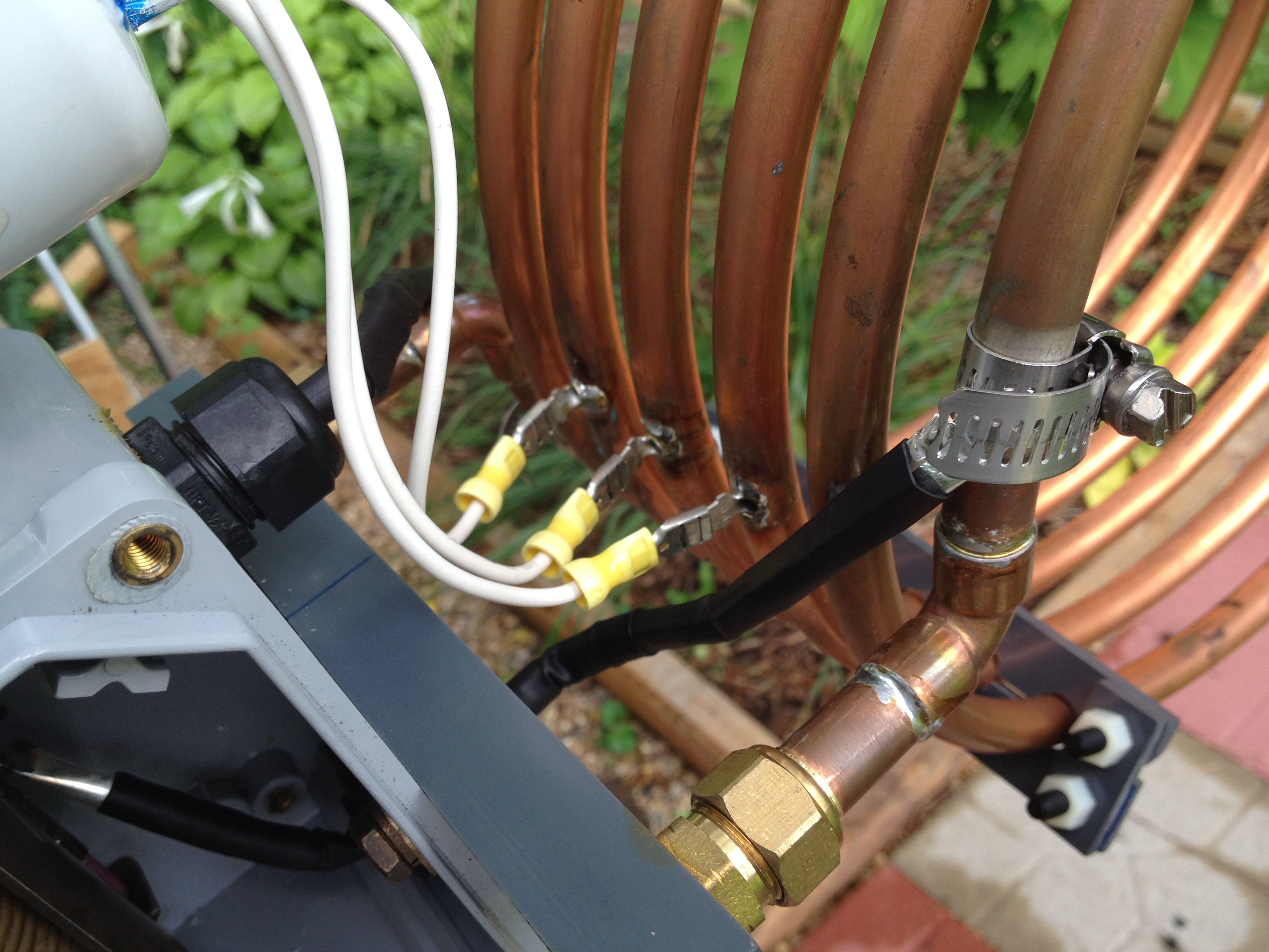
The loop tubing was drilled in 3 places to accept the barrels of male 1/4″ quick-connects, and these joints were then soldered. The loop amplifier is connected to these lugs. Note that this connection forms a 3:1 voltage transformer to the amp which results in a 9:1 amplifier input impedance transformation. The approximately 1 Meg amplifier input resistance now appears as a 9 Meg load on the capacitor-winding tank circuit which helps to keep the loaded Q high.
In starting this project, there were some known knowns. Primarily, I was pretty confident that a loop winding could be fabricated which would give me the proper inductance while at the same time giving me a required Q of around 3000. This build has proven that to me. There was also a major unknown known. It is extremely difficult to find hard data on the real Q of a mechanical variable capacitor of this type. The tubes are littered with vague statements which describe the Q of such caps as “very high”, “excellent”, and so forth. There are a couple of sites which have detailed Q information on a particular cap (which looked promising to me). But not this cap. Having built this loop, back calculations seem to suggest that the Q of this cap is somewhere around 1200-1500 at 6925 kHz, and this figure seems realistic to me.
My goal in this build was to raise the Q of a receiving loop by a factor of 2 or 3 from its current value of 250; I would be happy for a Q of 600. This would give an 3 dB BW of around 12 kHz at 6925; good, but not good enough to pry a pesc off of a pirate’s signal. So, what did we get?
To be honest, these results are preliminary, and vary all over the place. This is to be expected for such high Q circuits. The measurements can be tricky, and the results can be skewed by environmental things such as humidity, proximity to other objects, etc. At this point, Q measurements are consistently falling into a range between around 600 and 1050. I most commonly see values around 850 at 6925 kHz, and this thrills me to no end. A Q of 850 implies a 3 dB BW of around 8 kHz at 6925; if you squint, you can imagine that with a little more Q, some serious frequency discrimination can be accomplished.
How much more Q? I would LOVE to have a loop which exhibits a real 3 dB BW of 6 kHz at 6925; this would require a loaded loop Q of around 1150. At this point it is beginning to look realistic to me.
How do you get there with the current build configuration? One can calculate that at the current operating point (6925 kHz, Q = 850) that the LC tank circuit has a total effective series resistance of around 0.57 Ohms. I have gotten the greatest Q gains in the prototype by monkeying with the 2 connections between the winding and the capacitor, and I think that there is room for improvement there. Every milliohm counts. This particular capacitor also has the same Achilles heel that many variable caps have. the connection to the rotor. In this cap, there are 2 silver buttons on a spring loaded leaf, and these buttons wipe a silver commutation ring on the cap rotor. I have yet to do a really thorough cleaning of the sulphide layer on the ring, and have left this trump card in the back pocket. When I can no longer push the Q any higher, we will look here. There is also the possibility that this wiping contact can be replaced by a flexible silver tape, soldered to the ring.
There is a backup plan. This loop was built rigidly so that it would run in a stable manner at its tuned operating point. This would be a requirement for the next step, which would be to upgrade the loop to a so-called “regenerative loop” which could possibly supply some additional Q. More about this later.
In the few nights that I have used this for DXing, I have started to become familiar with the listening characteristics of this loop as compared to my standard loop. Although my current Neanderthal tuning supply makes it hard to peak the loop on a signal, the response peaks as seen on an SDR FFT plot are much more pronounced at Q=850 than they are at Q=250. With a 100 kHz view span, the 250 loop gives you a pretty good heads up look at a wide chunk of frequency spectrum; it’s hard to miss a weak signal off to the side of the loop response peak. Not so with the 850 loop; signals off to the side may be attenuated deeply, and it is quite possible to miss stuff.
On strong signal reception (say >= S7) it appears to be a coin toss between the 2 loops; both perform adequately. On weaker signals, I am giving the preliminary edge to the 850 loop. The 850 loop appears to be giving me better S/N ratio on weak signals, but I will hold this call until we are deeper into the season and storm noise lessens.
Which brings up another observation: when I had a wire antenna up, I noted that storm QRN as heard via the 250 loop was a lot “softer” than the crashes heard via a wire antenna. In the headphones, the storm noise was still there, but it tended to be less harsh and grating on the ears, and it was easier to “hear through” the noise on the 250 loop. I am noting now that storm QRN heard via the 850 loop is even mellower than that heard through the 250 loop. There is something going on there, as there is even a difference in lightning strike rendering in the SDR waterfall.
Well, enough for now.