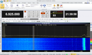
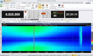
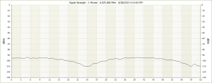
Resonant Loops (RLs) are an often overlooked form of receiving antenna, but remain my favorite, both from a performance viewpoint and also from a viewpoint of passion: I love the things! Although they are not by any means as popular as their remote cousins, the Shielded Magnetic Loop (SML), RLs can in some environments offer performance which an SML simply cannot match. With careful design and construction, RLs can exhibit a very high loaded Q which can give the loop:
1) A very high degree of frequency selectivity right in the antenna, often to the point where additional front end filtering is not necessary to protect the receiver from spurious responses. Case in point: in my area, there are a number of 50 kW MW stations, and to use my Wellbrook SML for NDB DXing, I MUST use a 9th order lowpass filter. Such a filter is not needed when DXing NDBs with a Ferrite Rod RL.
2) A very low Minimum Discernible Signal; RLs can have a sensitivity which belies their size.
3) RLs tend to be amplified loops, but a high Q in the antenna can drastically reduce the gain requirements of the following amplifier.
4) A well balanced RL will generally exhibit strong directionality. In some loops at some frequencies, an RL can discriminate reception based on the arrival azimuth. Peaks and nulls may be observed. At the very least, an RL can discriminate against local noise, and I have observed noise depression of up to 30 dB when I have had an RL mounted on a rotator.
5) An RL tends to be small, and can generally be sited in a quiet area on one’s lot to keep it away from power or utility lines, houses, etc.
As well as their advantages, RLs as a receiving antenna have a number of disadvantages.
1) Without band switching (and this is not always feasible), RLs have a finite tuning range (Fmax over Fmin), and this is generally within the range of 3:1 to 5:1. This tends to make an RL an “Application Specific” antenna.
2) The lack of commercial offerings means that you are most likely going to have to roll your own; RLs tend to be a construction project by the user.
3) There are countless gripes on the internet by users who dislike the fact that they must be re-tuned constantly as the receiver frequency is changed. They have missed the point by a country mile; the magic in a RL is in its narrowband nature and mo’ narrow mo’ better. Generally.
4) Although physically small (we are talking about small receiving loops here), to fully realize the sensitivity which a small RL can offer, the RL MUST be sited outdoors. This complicates the tuning of the loop, as the capacitance used to tune the loop MUST be located physically close to the loop winding. Using varactors to tune a loop remotely is pretty easy, but if the target Q of the loop requires the use of a mechanical variable capacitor (as this LF Ferrite Loop does), then it becomes a substantially more complicated process to tune the loop remotely.
5) RLs are generally considered to be unshielded and thus prone to signal corruption from local RFI. This is not true, and most resonant loops can be built with an effectice electrostatic shield.
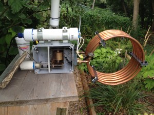
Over the past winter and spring, I have been working on a prototype of a Ferrite Rod RL which would be suitable for DXing LF NDBs. Some of the progress and logs have been posted here:
http://www.hfunderground.com/board/index.php/topic,19471.0.html
http://www.hfunderground.com/board/index.php/topic,19868.0.html
http://www.hfunderground.com/board/index.php/topic,20896.0.html
I have been extremely encouraged by the performance of the prototypes, and have been working on a “Generation 3″ version of the loop which should be deployed by this fall. I cannot do much about the first 2 “disadvantages” listed above, but the G3 loop and its control system are being designed to attack problems 3 and 4 head on, and offer some functionality which will greatly aid in the DXing of LF NDBs. Some of the key points are:
1) Design of a Stepping Motor Gear Train which will allow precise tuning of a mechanical variable capacitor located out near the loop site (about 160 ft away). In the current design, there are approximately 4800 motor steps per full 180 degree traverse of the tuning capacitor, which is just about the minimum required for the loaded Q of this Ferrite Rod RL.
2) Utilization of an Arduino SBC in the loop head. The Arduino firmware implements a Server (a simple command interpreter) which will control the Geared Stepping Motor used in the gear train via a standard off the shelf Stepper Shield for the Arduino. It will also allow control of additional loop parameters from within the shack.
3) The system will be controlled (tuned) via a Client application which will run on the same computer as the SDR control app (at this point I am using SDR Console V 1.5). At this point, RC is coded against a small subset of the SDR Console CAT Command vocabulary, but more is possible in the future.
n.b. There have been a large number of design decisions to make in this project. The choice of the SDR control program to code against (at least initially) was kinda critical. I have 2 favorites: SdrDx and SDR Console, and I have been able to programmatically control both via apps I have written. As good as SdrDx is (and it is very very good), I prefer using the older version of SDR Console (the version with the infinite license) for NDB DXing. Its ability to present full screen views of the waterfall and spectrum without control clutter is a huge aid in DXing, and its ability to simultaneously display a Zoom window with a span of 2 or 5 kHz really aids in fine tuning a loop. Additionally, I really love the palette control in SDR Console; quick very fine adjustments in the palette allow the app to function as its own QRSS viewer, and the ability to visually DX piled up NDBs really lessens the fatigue you encounter when trying to hear a particular NDB in a pileup. The fact that communication with SDR Console is easy via a free Virtual Serial Port Manager (such as VSPE) is a big plus.
4) The Client app (at this point boringly named Remote Controller or RC) will encapsulate a number of functional blocks in individual Tab Pages in a TabControl in the following categories:
A) Server Connection/Transactions: This page contains the controls to open, maintain, and handle a network connection to the Loop Server out in the yard.
B) Tuning/Memory Lists: RC will implement a set of tuning controls, some of which are programmable, to accomplish Loop and Receiver tuning. RC will enable the user to create Memory Lists which are displayed in a ListView Control, and which can act as a tuning source by double clicking an item in the list. I consider this to be a very powerful feature which might help in DXing NDBs this fall. I imagine loading in a general list of NDBs at the start of a session to gauge what cards the Great Gods of Propagation has dealt out. From these “prop beacon beacons”, I might determine, for example, that commonly heard stations in Nunavut are in well, and I could then prepare (or load in a previously prepared) Memory List of Nunavutian NDBs to see if I can hear anything new without having to navigate through the online RNA list.
C) Station Database: In NDB DXing, I find the RNA NDB list to be absolutely indispensable. RC has the ability to import a prepared copy of the RNA Excel download file, and this list is displayed in toto on a tab page in RC. RC displays the list in a CheckedListView Control. Double-clicking an item will execute it (tune the Loop and also the Receiver to the NDB frequency). Individually selected items can be checked and exported to a Memory List. The list is searchable (by call with wildcards, by ITU country, by State/Province, etc.). Search results can be exported to a Memory List. This means that it is a very simple process to generate a custom Memory List for all NDBs in Alaska, for example.
D) Receiver: RC can open and maintain a connection via a Virtual Serial Port to the SDR Console app running on the same Windows box. Tuning the loop can simultaneously tune the SDR to the RL resonant frequency (right now the accuracy is about +/- 2 kHz), but fine tuning of the loop is easy. In fact, in NDB DXing, the RL is more often than not tuned to one of the sideband frequencies, and not the carrier referenced in frequency lists.
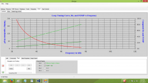
E) Calibration/Testing: Since a calibration curve of the antenna response (motor steps versus resonant frequency) is required, RC contains Antenna Calibration functionality which allows a semi-automated approach to antenna calibration. Calibration Curve data can be viewed graphically. RC also implements a number of built-in test suites which can be used to test the loop, receiver, and rotator performance, and can help the app to function as a tool for further development.
F) Rotator/Amplifier: Since RNA logs also contain a Maidenhead Locator field, from this Longitude and Latitude can be easily computed; this allows further computation of both Bearing to the NDB and also Range. I am adding control of a modified Antenna Rotator to the client app RC so that selecting an item in either a Memory or RNA list would (with one double-click) tune the Loop, tune the SDR, and rotate the Loop to the proper Azimuth. Rotation can then be manually controlled once it is at the proper az.
G) Profile/Settings: RC supports a Profile file, and uses it to store settings between sessions. The user can generate a profile which can be used to control various types of loops.
H) Normally, a Memory List item will contain all RNA fields, and when double clicked, the antenna and SDR will be tuned, and the rotator will be spun to the azimuth which can be computed from the RNA Maidenhead locator field. This azimuth will be the bearing of peak rod reception, but more often than not, this will not be the desired antenna bearing; one would in theory like to rotate the antenna to the bearing which will possibly give the best reception considering all of the co-channel NDBs which would interfere with the desired NDB. The loop generally has a broad reception peak and a narrow null (or depression) minima, and we would like to have these in the proper orientation with respect to co-channel interference.
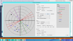
RC incorporates a Scenario Visualization tool. Right clicking an item in the RNA list will open the Visualization dialog. This will present a polar plot of Bearing vs Range on which all potentially interfering NDBs will be plotted, as well as the target NDB. The plot will also render markers representing the Peak and Null beams of the antenna, and these will be rendered with variable width beam widths. The antenna patterns can be rotated with respect to the plotted NDBs, and the user can select a best guess antenna rotation for the target NDB. This target RNA entry can then be exported to a Memory List, and any time the item is double clicked in the Memory List, the rotator will be rotated to the preferred (and not the Maidenhead) azimuth. This will enable me to create Memory List of highly desired high value targets, and will allow me to efficiently check these targets in any DX session.
A Block Diagram of the system is:
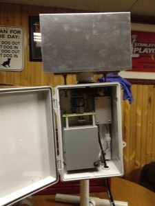
Well, that is an overview of what is going on here. This post will be followed up by at least 3 more posts. The first will discuss some of the technology in the Ferrite Rod RL (the wound rod, the capacitor, and the amplifier) and its tuning mechanism. That is pictured below in a weatherproof enclosure. The rod per se is not visible, but is located within the aluminum shield above the enclosure.
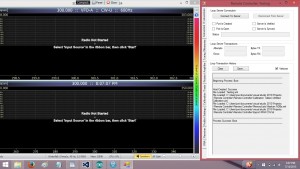
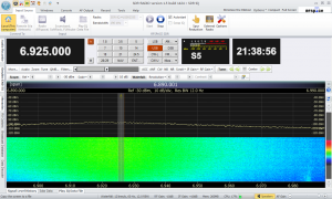
The second will discuss the Client app to a greater degree, and a screencap of a typical presentation (along with the typical SDR Console window) is:
The third will most likely discuss interfacing strategies, as this loop is sited a fur piece from the house, and requires and RF coax, power cabling, and also some form of digital network over which the client and server communicate
I am getting lazy in my old age, but we will most likely throw up a post detailing Rack Shack Rotator modification (converting from the ghastly and slow synchronous motor to a PM DC gearmotor, adding a position feedback pot, and a simple closed loop controller based on an Arduino Pro Mini controller which may be hosted by the Loop Server).
Additionally, the Scenario Visualization tool will most likely merit its own post. This has been one of the funnest parts of this project, and I foresee this tool being a great aid this next season.
There is also a long laundry lists of enhancements on the back burner, and we might get around to posting some of these ideas in the future.
Further on down the line we can post some results with regards to performance; there is a lot to evaluate.
This has been – and continues to be – a ton of fun, and also hard work. This antenna represents “where I always wanted to be” with regards to Resonant Loop antennas. This is a big step up from what I used last season, and there is still enormous potential, and lots of new functionality to imagine and implement.
If only the freakin’ thing works…


