Virtually all homebrew transmitters are crystal controlled. This is excellent from a stability point of view, but creates the difficulty of having to obtain the crystals. Usually this involves hunting around hamfests and swapmeets, hoping you’ll find a crystal of a suitable frequency. This can be hit or miss, especially for “out of band” operation, like 43 meters, where it is more miss than hit.
I’ve done some experimentation with building my own Phase Locked Loop frequency generators, but the results were always dismal. I recently came across the CY22150 Programmable Clock Generator from Cypress. This single IC implements the PLL, divider circuits, and everything else. You just need a crystal for the reference (there’s a built in oscillator). And the crystal can be virtually any frequency.
First, you may wish to look at the CY22150 Datasheet
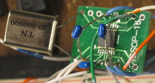
The CY22150 is in a TSSOP-16 SMD package, which is not very hobbyist friendly. I bought some of these adapters from eBay, which make the task of prototyping much easier. The CY22150 itself is available from Mouser and is $2.55 in single quantities.
The CY22150 uses an I2C serial interface to configure the various settings. For my experiments, I connected it to a Raspberry Pi single board computer. You could bit bang the I2C commands out the parallel port of a computer as well, if you wished. The CY22150 can also be programmed using Cypress supplied software, so no I2C interfacing is required. I have not tried this, but it could be useful in cases where operation on only one frequency is required.
I soldered the CY22150 onto the PCB, and attached it to the Raspberry Pi, which also provided the 3.3 volt power:
Several registers in the CY22150 control the PLL, and set the output frequency. You have to compute three divider ratios. There are also several other settings, and I’ll go through them below:
First, after powering everything up, you need to enable one of the outputs. In my case, I am using Clock Output 1, so I need to set register 09H to a value of 01H.
Second, I need to specify the source of this output. The datasheet refers to this as the “Crosspoint switch matrix control”, and the end result is setting register 44H to 20H, which tells the chip that we want the output to be DIV1CLK divided by DIV1N.
Third, we need to set the chip to use the internal oscillator with a crystal. In my case, a 20 MHz crystal. We need to set the oscillator gain level, based on the crystal frequency. Referring to the datasheet, we need the gain bits to be 10, and the end result is register 12H is set to a value of 30H. I played around with these values, and did not find them to be critical.
Fourth, we need to set the input load capacitor control. These are equivalent to the small (10 pF or so) capacitors you connect to the crystal in an oscillator circuit. What nice here is that we don’t need any external capacitors, they are built into the chip, and we can select the values to use! Register 13H sets the capacitor value. And, we can adjust their value to move the oscillating frequency, so we can get it dead on. In my case, for a 20 MHz crystal, I needed to set register 13H to 8F.
Here is the 20 MHz oscillator output signal, looking at XOUT pin of the CY22150:
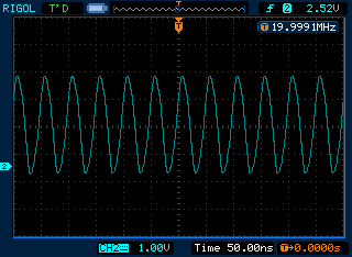
I finally get to use the screen capture mode of my Rigol scope!
Now it gets a little hairy. We need to compute the divider ratios. The datasheet shows you how to do this. I found some source code on the net that calculates the values for you, as an iterative process. There are multiple divider ratios to produce a given output frequency, the code finds the best set and smallest frequency error.
First, here is the C source code:
int main(int argc, char **argv)

{

double f_ref;

double f_out;
if (argc != 3)
{
fprintf(stderr, "usage: cy22150 refFreqkHz outFreqkHz\n");
exit(1);
}
f_ref = atof(argv[1]);
f_out = atof(argv[2]);
fprintf(stderr, "f_ref %g kHz\n",f_ref);
fprintf(stderr, "f_out %g kHz\n",f_out);
f_ref = 1000.0*f_ref;
f_out = 1000.0*f_out;
fprintf(stderr, "f_ref %g Hz\n",f_ref);
fprintf(stderr, "f_out %g Hz\n",f_out);
double q_min = 2;
double q_max = (int)(f_ref / 250000.0);
double d_min = (int)(1.0 + 100000000.0 / f_out);
double d_max = (int)(1.0 + 400000000.0 / f_out) - 1.0;
double f_test, f_diff;
double f_track = f_out;
double p_test, q_test, d_test;
int p, q, d;
for (q_test = q_min; q_test <= q_max; q_test++)
{
for (d_test = d_max; d_test >= d_min; d_test--)
{
p_test = (f_out / f_ref) * q_test * d_test;
p_test = ((p_test - (int)p_test) > .5) ? (int)(p_test + 1.0) : (int)p_test;
f_test = (f_ref * p_test) / (q_test * d_test);
f_diff = ((f_test - f_out) > 0.0) ? (f_test - f_out) : (f_out - f_test);
if (f_diff < f_track)
{
f_track = f_diff;
p = (int)p_test;
q = (int)q_test;
d = (int)d_test;
fprintf(stderr, "p:%d ",p);
fprintf(stderr, "q:%d ",q);
fprintf(stderr, "d:%d ",d);
fprintf(stderr, "f_test:%g ",f_test*0.001);
fprintf(stderr, "f_diff:%g \n",f_diff*0.001);
}
}
}
exit(0);
}
Running it for 7175 kHz produces the following output:
$ ./cy22150 20000 7175

f_ref 20000 kHz

f_out 7175 kHz

f_ref 2e+07 Hz

f_out 7.175e+06 Hz

p:39 q:2 d:55 f_test:7090.91 f_diff:84.0909

p:39 q:2 d:54 f_test:7222.22 f_diff:47.2222

p:38 q:2 d:53 f_test:7169.81 f_diff:5.18868

p:33 q:2 d:46 f_test:7173.91 f_diff:1.08696

p:113 q:7 d:45 f_test:7174.6 f_diff:0.396825

p:221 q:14 d:44 f_test:7175.32 f_diff:0.324675

p:287 q:16 d:50 f_test:7175 f_diff:0
You call the program, passing it the frequency of your crystal, and the desired output frequency. It then goes through a few steps, and finds the best match.
The divider ratios are p, q, and d. In this case, they are 287, 16, and 50 respectively. These need to be set in several registers in the CY22150:
Ptotal (p) is the most confusing. We actually have to calculate what the datasheet refers to as PB and PO. The formula is P total = 2*(PB+4) + PO. In our case, we have 287=2*(PB+4) + PO. So PO is 1. Then we solve 286=2*(PB+4): 143=PB+4, or PB=139. That's 8BH.
PB goes into registers 40H and 41H. The high two bits go into 40H. You also need to write three charge pump control bits into 40H, and set the two high bits of 40H. In our case, the two high bits of PB are zero. So we just need to set the two high bits and the charge pump bits. From the datasheet, we want to write C4H. We also need to write the low bit into register 0CH when we set the D divider ratio, below. The 8BH value we calculated above goes into register 41H.
D goes into register 0CH. 50 decimal is 32 hex so we write 32H.
Q goes into register 42H. PO goes into the high bit. You actually have to write Q-2 into the register, so we need to write 14 decimal, which is 0EH. Plus since PO is 1, we set the high bit, so we end up writing 8EH.
Whew!
We ended up with these register settings:
09: 01  Enable output 1

0c: 32  D = 50

12: 20  Xtal drive

13: 8f  Load capacitor set for accurate 20 mhz

40: c4  Set two high bits, bits 2,3,4 are charge pump, 4 is the correct value based on P

41: 8b  PB=139

42: 8e  Q of 16, so we set to 16-2=14, set high bit because PO (low bit) of P counter is 1

44: 20  Set the output to be DIV1CLK / DIV1N
For fun, you can also compute the divider ratios for say 6925 kHz:
p:277 q:16 d:50 f_test:6925 f_diff:0
Note that these values are based on a 20 MHz crystal. If you use a different value, they will be different. But that's the great thing about this chip, you can use whatever you have!
Here is the scope looking at the CLOCK 1 output :

And here is what it looked like on an SDR-14:
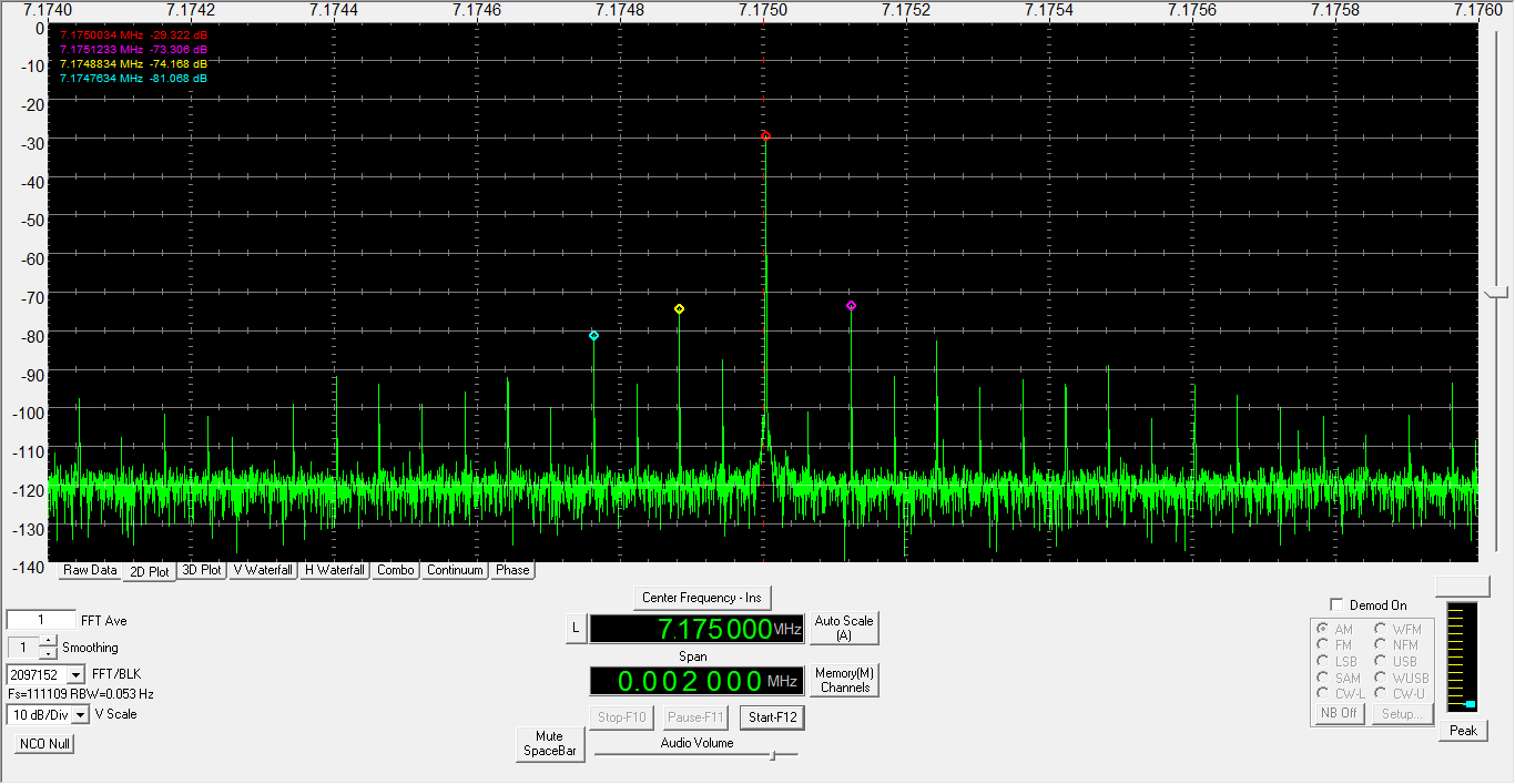
As you can see, I do have a 60 Hz pickup issue to solve. No doubt due to the rats nest of wires. But... it works!
Since the Raspberry Pie may be overkill for many homebrew transmitter applications, another possibility, besides programming the Cy22150, would be to use a inexpensive microcontroller such as a PIC to send the I2C commands to the chip. I may look into this as a future project.