Basic Info & Radio Hargeysa (non-Clandestine)

Ok – a bit about me & my location: I’m near Chicago, IL USA. I use a Drake R8, a Ten-Tec RX340, a JRC NRD545, and a Watkins Johnson HF-1000, with a 300′ tuned LW, and a 40m inverted vee, plus a bunch of gadgets (Sherwood SE-3s, JPS NIR-12, Timewave DSP 599zx, RF Systems P-3).
I’m 52 and have listened to SW since I was about 10. Unfortunately I didn’t start a written log until 1992 or so. I have logged many clandestines, concentrating on chasing African stations. I have a lot of recordings & I’ll be posting them from time to time.
As we get near fall, conditions should improve greatly – work typically keeps me off the tuning knobs Mon-Fri 6am to 5pm CT. I’ll try to post a heads up of clandestine activity on here as I confirm schedules for the fall.
I tend to use whatever schedules I can find on the web (EiBi, Primetime SW, swskeds from NASWA via yahoo, etc.).
Here’s Radio Hargeysa (VO Somaliland) from Somalia that I caught on 3/17/13 at 0330z on 7120khz. You’ll notice they come up at the BOH into marching music, then drums with the same music, into an OM in Somali language, then eventually chanting. Though not a clandestine, catches like this indicate openings in the right direction! This is a slice of the recording that I have.
I hope that you enjoy my blog and find the recordings of interest.

Radio Miraya FM

Hello all – here’s a sample of a clandestine I caught on 3/17/13 at 0300z 9940khz. This BX is via the Sudan and is directed to Africa in general. Interesting that it pops up out of static into a song in progress then transitions to Dylan’s “Lay, Lady, Lay” before the first voice announcement, then into music. The full recording contains the entire Dylan song, but I edited here for brevity.
Recent feedback indicates this is NOT a clandestine though sources still list it as such. Strange.
I have more of this recording – this is just a slice.
I hope that you enjoy it.

SAM_0110

Teaching LULU to Sing – AM Modulation


I hope you’ve had success with LULU so far.  If you are building for CW use, then you’re done.  However, this time around we will be a-modulating so we need to discuss some construction techniques before we start.    Most builders aren’t as anal about RFI prevention as I am when building rigs yet they rarely have problems.  I have experienced that too.  However, I have also spent many hours trying to hunt down the source of hum, or whine, or RF hash that is stubbornly haunting my project.   I have had rigs that worked fine for a time, then a bypass cap opens up… somewhere, and I’m off playing the feckless RFI hunter again.  My philosophy is this:  if you overbuild as you go along, the odds of having problems later on are greatly reduced.  In that spirit, I give you some RFI-fighting tips to consider as you lay out your chassis pan.  Best case would have the entire RF strip mounted inside a small metal box or RF shield inside the larger enclosure.  With LULU being so compact and cool running (Class E), a large enclosure is not needed.  And in this way, that sassy little hash generator is kept under wraps.  Second, any signal wire runs use shielded wire that is grounded on ONE end only.  Other long runs are wound through ferrites.  And third: redundant bypass caps are used at most input/output ports in the chassis.  Most of this is probably unnecessary, but I sleep better.  Maybe you will too.

SAM_0109


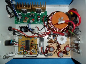
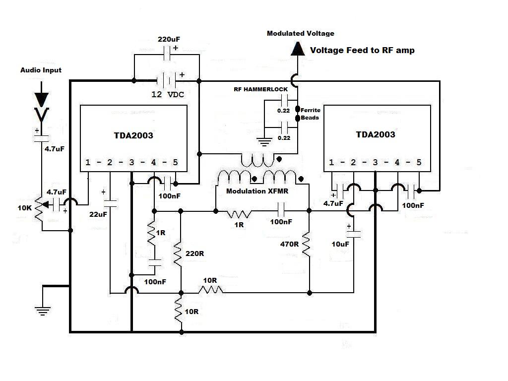
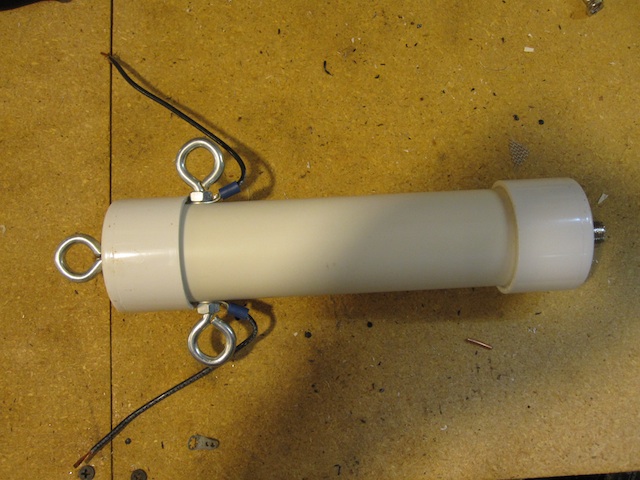
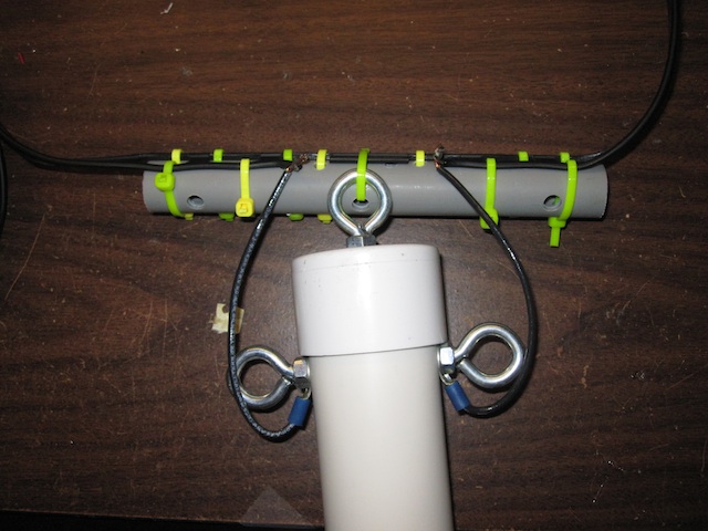
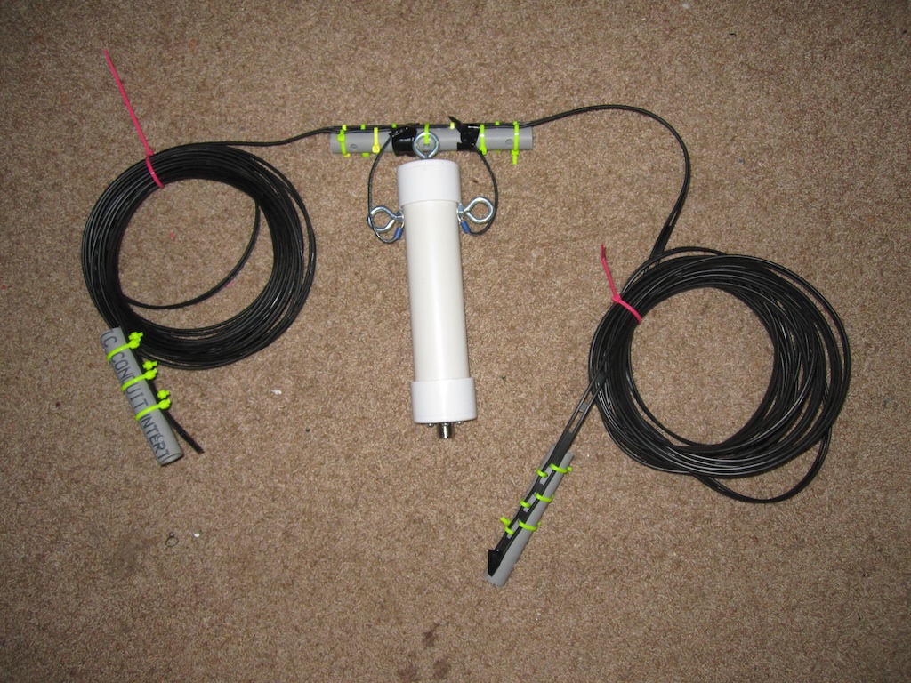
Purposely for this build I have IGNORED most of these “extras” as you can see in the photo.  I have kept the RF hammerlock in the modulated voltage line, the shielded audio input lead, and most of the bypassing caps – you should too – but I have left out everything else including all ferrites.  I have experienced no problems.  But this build was to illustrate this article and will rarely be used.  Any of my serious builds utilize all those tips I just gave you.  It’s your choice.


AUDIO AMPLIFIER

LULU Bridge Audio


In the past, little rigs in the 10 watt realm were modulated with a monolithic amp chip in a single-ended configuration.  Unfortunately, the typical LM383 or TDA2003 starts gasping for air before the modulator’s peak power needs are met.  Also, with a single-ended configuration, one side of the modulation transformer’s audio winding is grounded, which under some conditions can form a ground loop and cause a lot of hum.  The better way to modulate is to use a pair of TDA2003s in a bridged amp configuration.  This solves both problems.  The bridged pair circuit is shown above.


I have probably built half a dozen of these and they work well.  However, I have a better solution for you.  Cana Kit now features the bridged pair in kit form for 20 bucks plus shipping http://www.canakit.com/20w-bridged-audio-amplifier-kit-ck193-uk193.html.  That pre-made circuit board will save you a tremendous amount of time and cursing.  I will never build one of these from scratch again – ever.  Only you can determine what your time (and sanity) is worth.  A second option: Parts Express has a Bridgeable Class D Amplifier kit for 20 bucks that uses the Texas Instruments TPA3122.  I am just now experimenting with my first one of these.  I don’t know if it will survive as a modulator over the long haul.  Caveat Emptor…


MODULATION TRANSFORMER


Back in the day Boomer the Radio Animal rewound the venerable Radio Shack hash choke to use in his Grenades.  Unfortunately, they are no longer available.  Dave Martin uses a transformer pulled from a now defunct Taxi radio for his Commandos.  They aren’t available Stateside, and now sources in the UK seem to be drying up too.  Wind-able transformer iron in the small size range is tough to find.  You can find a lot of cores with interleaved E and I sections, but none with the separate parts like the old RS hash choke had.  There are a few websites that show how to separate interleaved cores.  I’ve tried it.  It’s about as do-able as shoving a wet noodle up a wildcat’s butt.  I decided to sidestep this whole issue and develop a toroidal transformer that would modulate well.  This is not a new idea.  However, most folks shy away from toroids because they are hard to wind, should you need a lot of windings as with a modulation transformer.  I’ll let you in on a little secret – they’re hard, but not THAT hard.


There are two downsides to using a toroid for this.  One: good luck trying to find a T200-26 core locally.  You’re gonna have to order one (or two?) from CWS Bytemark.  At this time they’re only about 3 bucks apiece.  You can stock up on your T50-2s and T80-2s on the same order.  Two: They take up a lot of space.  With the windings, it’s going to hog a footprint of 6 or 7 sq in.  The upside is that the audio is decent and the coupling is good enough to allow full modulation of LULU’s carrier signal.  Also, the #26 material has flat response across the entire audio range.


The “mod tranny” is basically an impedance matcher.  Your tranny’s winding ratio will depend upon how good a tweaker you were when building LULU’s RF strip.  If you feel unworthy because you could only get 8 or 10 watts out, then cheer up.  Your winding task will be much easier than that of the overachiever.  And you thought more was always better…


For up to 12 watts of RF output a 1:1 impedance ratio will work fine.  The amplifier has plenty of power capability to compensate for any mismatch.  Cut a couple of 7.5 foot lengths of 18 gauge magwire.  Secure one end of each in the chuck of a variable speed electric drill.  Secure the other pair of ends in a vise, or vice grips, or between your spouse’s teeth.  Using short bursts of the drill, spin them together until they have a couple of turns to the inch or so.  Then wind both windings at the same time.  Keep the turns tight to each other on the INSIDE of the core with no overlapping.  I was able to get 42 turns on the one in the photo.  Less stress…  Less pain in that arthritic wrist…


If you were able to tweak more output from LULU then you’ll need two separate windings.  And this one really IS a tedious transformer to wind.  Wrap the audio winding first.  You should fill the INSIDE of the toroid, keeping the turns tight with no overwinds.  If you use 18 gauge magwire you should be able to get about 80 turns on it.  A single layer of masking tape wrapped around the outside (like a belt) will help hold the windings in place.


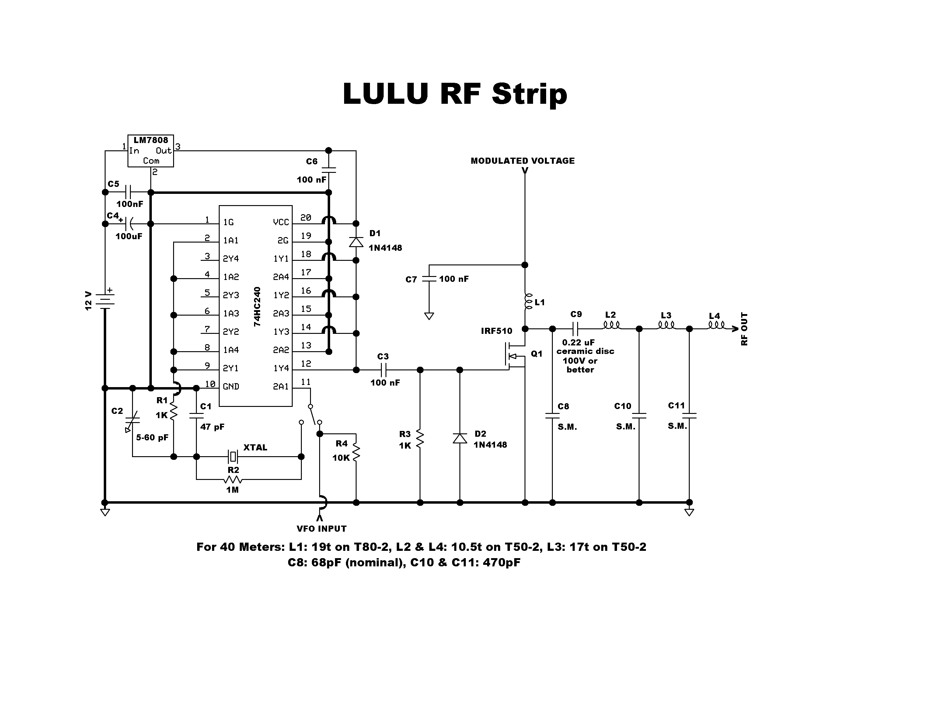
To calculate the DC winding, first get a decent measure of your RF output BEFORE the harmonic filter (at the C9/L2 junction).  To find the approximate impedance at that point:


1)      Square the input voltage (12 * 12 = 144) and then divide the result by TWICE your measured power.  For example, if you measured your unfiltered output at 16 watts, your drain impedance would be approximately 144 / 32 = 4.5 ohms.


2)      The output impedance of the bridged audio amplifier is 8 ohms.  So the impedance ratio for our example would be: 4.5 / 8 = 0.5625.  Then take the square root of that result (0.75).  This is your required turns ratio.


3)      If you have an 80 turn audio winding, multiply that by the turns ratio (80 * 0.75 = 60).  You need 60 turns of wire overtop for your DC winding.  I should tell you to spread it evenly around the toroid.  However, it is mighty hard to do.  Just wind it as best you can WITHOUT OVERWINDS.  Admittedly this will take patience.  But hey, you only have to do it once…


PRE-PROCESSING


If you use LULU as is you will be a “wide Clyde”.  For AM communications work you must neck the audio down.  An outboard mic preamp or speech processor with a 3KHz audio cutoff filter is recommended.  For program content, the audio input is set up to receive a Walkman or MP3 player type output.  Pre-processing should be considered for increased readability of your signal.  Most audio software will do a good job.  Personally, I use Audacity to add compression and to roll off the highs above 8KHz with the EQ.  If you are a live kind of guy or gal, processing should be done at line level following your mixer.  A small line amp built from an LM 386 or similar can then boost the processed signal to LULU’s required drive level.  Good luck with this, have fun, and be safe out there!


Welcome to the Clandestine section!

Hello all,
While I am in NO WAY an expert on dxing clandestine stations, I have concentrated on this area of SWLing for the past 20 or so years.
I figured I’d start out by telling you a bit about myself, my equipment, and the “tools” I use to find info about clandestine station broadcasts.
At some point I’d like to be able to “post” some mp3s of recordings that I have made over the years – many of which are of clandestines that are now long gone. I’m not real computer literate but hopefully I can figure it out (my recordings are on Sony Mini-Discs and I have Audacity on my computer that will convert wav files to mp3 files – I think…. If someone can offer me info on how best to make these mp3s available, I would be very grateful and I can promise that everyone will find these recordings interesting).
Though I am also a numbers station enthusiast and have logged many over the years, I don’t plan on discussing that aspect of our hobby and will instead concentrate on what (I think) we all consider “true clandestines”.
I hope that you will find my blog informative, entertaining, and useful in your own hunting for these stations. Thanks.

Time to Call the Service Guy

After a rather moderate summer, Chicago has seen the appearance of a couple of spells of nasty heat and humidity. Along with this I have noted the appearance of a new noise in the 43 meter band and elsewhere. It is typically noted at around an S5 level with my resonant loop spun to the preferred azimuth. It begins in the late afternoon, chugs away at a rather high duty cycle for a couple of hours, and then settles in to a low duty cycle operation (a few minutes every hour) by 0100z. It has every indication that it is mains-related, and did not correlate with anything in my house. In the past I have had problems with leaky or grunged insulators on utility power poles, and the noise resulting from that has always exhibited a more random and intermittent nature; it has also tended to exhibit strengths in the range of S9 to S9+5. This new noise was kinder and gentler, but would still interfere with my ability to note weak carriers in the SDR waterfall. When I come down to the shack after work, I like to see an S2 noise floor in the late afternoon, when storm noise is not audible, with my preferred SDR gain settings ( IF = +18dB, RF = -10dB ). This was not the case.

I have just recently installed a rotor on the loop, a HyGain AR-303 light duty rotator which can easily handle a loop of this size. The goal then was to see what could be done about dealing with and possibly identifying the source of) this noise.

A small loop exhibits a “Figure 8″ reception pattern; there are two lobes of maximum reception which are aligned with the plane of the loop. There are 2 reception “nulls” which are at right angles to the plane of the loop. In theory, these nulls could be pointed at an offending noise source to minimize its impact on reception. The “Standard Loop” described in the HFU post here http://www.hfunderground.com/board/index.php/topic,12084.0.html has been designed to offer a good balance of reception properties. While I have slanted the design towards sensitivity, there is still enough ability to depress local noise sources. Let’s see how much.

Maximizing the noise by loop rotation, this is what was seen on the SDR waterfall:

AC Noise

The brightening of the waterfall palette is clearly seen across the resonant bandwidth of the loop, and it is easy to see that weak carriers or signals about 6925 (or at any frequency in the SDR display range) would be obscured. The SDR is reporting an average signal strength of S5 at 6925. To be honest, this would not be an issue if everyone was heard at S9+10; there might be some background buzzing in the audio. But for DX, I could not live with this.

The loop was then rotated so that the noise was minimized, and another screen cap was taken. The waterfall now appeared like this:

No Noise

The noise about 6925 has been reduced significantly, and the SDR is now reporting a signal strength of S3 at 6925. This is a bit higher than what I would like, but I can live with that. Using a light touch on the SDR noise blanker helps to clean up most of the remaining audio buzz without introducing distortion.

Note also that a couple of things which were not visible in the previous image are now visible. The spur which we commonly see on 6970 is now there, as is a big blob of noise just above 6980. I do not know what this is, but I see it all the time. It generally hangs out around 6980 plus multiples of about 105 kHz above and below 6980. It generally stays close to this frequency, but it may move up or down and appear as massive interference at 6925. But it can be suppressed also. If you compare the previous image (max noise) and with this it can be seen that these two noise sources are at about 90 degrees apart in azimuth.

A better way to look at this would be by looking at the SDR waterfall as the loop is scanned. In a separate session (the following day) I again looked at these two noise sources by scanning the loop through approximately 180 degrees (from rotor north to rotor south) and taking took a screen cap of the entire scan. That is here:

Loop Scan 29Aug13

This image clearly shows that around the time the rotor was pointing due east (lobes of max reception pointing east and west, nulls pointing north and south), the noise was minimized, It also shows that the rough azimuth of the second noise source around 6980 could be determined from the rotor position. The lobes of the null are not sharp, and there is a spread of a few degrees where the noise is minimized as a consequence of the loop null pattern. The loop is dealing with the noise fairly effectively. It seems to indicate that a noise reduction of about 2 S Units (12dB) is being observed.

A more accurate way to measure the noise reduction was tried. I use SDR Console to support the SDR-IQ, and the most valuable tool this software has is a Strength History window. I set the Strength History range to 60 seconds, and again scanned the loop from rotor north to south, while the history window recorded the loop output in dBm. Here is what I saw:

Loop Scan 28Aug13

I currently have no way to calibrate the scan; I don’t know exactly when the scan started or stopped in the strength chart, but a rough guess would be that it started around 40 seconds into the chart, and ended around 10 seconds. No matter; the pattern minima and maxima are easy to see, and these are approximately -110 and -94dBm, a difference of 16dBm (approximately 2.6 S Units).

This is a typical value of the suppression which can be obtained against a local noise source. I have seen suppression against particular noise sources of up to 24dB (4 S Units), but this seems to be about the limit. I no longer freak when noise pops up; loop rotation can generally solve most of the problem, and judicious use of the software noise blanker generally cleans up the rest. As long as there is a reasonably wide azimuthal difference between the noise source and the desired station, effective noise reduction can be accomplished.

This was all done using an unshielded resonant loop; at some point in the future I would also like to try this with a Wellbrook loop.

It’s been a long boat ride here, but the noise source was pretty easy to ID by sighting through the loop. When the noise was suppressed, the null pointed directly at my neighbor’s air conditioning unit, and it looks to me like it’s time for him to call his service guy. I would be absolutely willing to do a quick and cheap fix for him with my Sawzall…

Northwoods Radio – Comparison of Two Transmitters

Northwoods Radio was on the air Sunday morning, September 1, 2013, running on 6935 USB and 6950 AM in parallel. The 6935 transmitter was at about 40 watts ladderline fed phased delta loop array. 6950 was about 7 watts into a dipole at a height of approximately 45 feet. This provided a unique opportunity to compare how well these two transmissions were received.

Below is a graph showing the signal levels of each, along with 6930 kHz, which was unused during this time period. The 6930 signal level provides a good measurement of the background noise levels during the broadcast. The signal levels were filtered, to reduce the variations in signal, otherwise you end up with a very messy and difficult to read graph:

The blue trace is 6930 kHz. It starts at about an S8 level, and drops to about S7.

The pink trace is the 6935 USB transmission, and yellow is the 6950 AM. According to Jackpine Savage, the Northwoods Radio operator, sign on was 1050 UTC. 6935 is first briefly audible around 1100 UTC, but extremely weak, not much about the noise floor. The operator noted that he increased the audio levels around 1100 UTC. Both become audible at 1110 UTC. As you might expect, both do fade in at the same time.

6950 is rarely more than an S unit above the noise floor, usually less. 6935 is about two S units above, sometimes more.

It is difficult to make direct comparisons, as there is always a carrier present with the AM signal, while the USB signal level depends to a great degree on the amplitude of the program audio. It may be best to look at the envelope of the USB signal level.

It is interesting to note how the background noise level, as well as the signal levels, all go down over time, dropping about an S unit over 2 hours.

A New Station – BOC HF RADIO

A new pirate station, BOC HF RADIO was heard yesterday, August 30, 2013 on 6925 USB starting at 2310 UTC. The station featured music from the electronic music band Boards of Canada.

The station was logged by quite a few listeners on the HF Underground Pirate Radio Message Board
The station opened with a PSK125 transmission:

RYRYRYRYRYRY I AM GLAD that my signal has reached such a far audience! I was not expecting such a turn out for te teS t _eP show. I couldn’t help myself, I have to go up again! I will be playing a new album, a favorite of many: TOMORROW’S HARVEST by BOARDS OF CANADA Thank you for listening, everybody. -UNID

The second transmission began with this CW (Morse Code) message:

xxxxx/xxxxx/xxxxx/xxxxx/xxxxx COSECHATRANSMISSIONES BOCHF BOCHF BOCHF

And closed with an SSTV image:

The station operator send me the following eQSL in response to my reception report, which was sent to bochfradio@gmail.com

BOCHF1s

Here are recordings of the two transmissions from yesterday:

2310 UTC:

2340 UTC:

Somewhat Poor Propagation Today 15 Aug 2013

CFRX 6070 is a station I frequently use as a reference to see how the bands, particularly 48 and 43 meters, are doing. Normally it is about S9+10. It was only S6 around 1800z today, it since has improved to S8 to S9 at 1930z.

Another listener, in NH (so closer to CFRX) reports that they are barely moving the S meter there.

I checked the real time FoF2 map, http://www.spacew.com/www/fof2.html and the critical frequency (which is the highest frequency will be reflected directly back down) is only 6 MHz over most of the US, falling to 5 MHz over Canada. This is what you would expect with a depressed FoF2 frequency:

If this continues, 43 meters may be near useless for close in (NVIS) reception, especially as the critical frequency falls later in the day. More distant listeners would still be able to receive signals, but the K index is presently 4, which is close to storm levels.

A Sloped Folded Dipole Antenna for 43 Meter Band

While I’ve had very good reception using my sky loop antenna, I wanted something that would have better low angle radiation sensitivity, for improved reception of distant stations.

The sky loop is 670 ft in perimeter, and runs around the yard at a height varying between about 20 and 50 feet, depending on how tall the trees are. In order to get a better low angle radiation pattern, an antenna, for the 43 meter band anyway, should be higher. I don’t have two tall trees suitable spaced for erecting a standard dipole high enough for 43 meters. I do have one tall tree however, so I decided to consider a sloped dipole.

Below is the NEC simulation of a such a dipole:

The low angle radiation sensitivity is indeed pretty good, and there is some directionality as well.

I decided to go with a folded dipole, as my previous experience with them has been good, they seem to share the common characteristic of all loop type antennas of not picking up a lot of local noise and RFI.

A folded dipole is constructed using two conductor cable, such as TV twin lead or ladder line. I went with the latter as twin lead is not very rugged:

As the feedpoint impedance of a folded dipole is about 300 ohms, a balun should be used. In this case I used a 4:1 balun, which then feeds 75 ohm RG-6 coax:

I used some short sections of plastic conduit for the end and center supports, to provide some mechanical rigidity:

The standard dipole formula was used, resulting in a length of 67 feet. The two far ends of the ladder line have their insulation removed and the two wires are shorted together.

At the center of the antenna, one of the conductors is cut, and the balun is attached here, as shown below:

I used nylon wire ties to secure everything.

Here is the completed antenna, the two sections of ladder line are temporarily spooled to keep them tidy until the antenna is erected:

The high end of the antenna is at about 55 feet. the low end about 15 feet. A rope is attached to the balun eye hook and goes over another tree, providing a little more mechanical support.

For normal daytime reception, it works about the same as the sky loop on 43 meters. At this time of the day, propagation is NVIS, and the signal comes down at a high angle. I was not expecting much of an improvement here.

Later in the day, results have been quite good, as I hoped. Late in the afternoon, I decided to try 6160 CKZN from St Johns, Newfoundland. With the sky loop, I barely had a carrier, while with the folded dipole, I had audio.

All in all I am quite pleased with the performance, and am switching to using this antenna for my overnight recordings on 43 meters.

Building the Basic LULU Transmitter


lulu-RF


I LOVE LULU


I have been happily turning mountains of electronic parts into scrap for nearly 50 years.  The quest for a well-performing, easy to build transmitter has greatly added to my slag heap.  After much pleasure and pain, I am pleased to present to you, Dear Reader, a transmitter that satisfies both criteria.  I offer you LULU…  Back around 2000, Norberto, an Argentine ham, put together several existing concepts and came up with the basic LULU design.   The LULU name is an affectation that came about in our builders group.  It is easier than calling it “an LU8EHA variant” as it was known for awhile.  We have made several changes to Norberto’s original design, but he would certainly still recognize it.


The heart of LULU is a 74HC240 octal buffer chip, which functions as an oscillator and driver.  Its gates are tied together to increase its ability to sink and source current.  Our active device is a MOSFET, which is turned on and off by swings of the input voltage.  We will be powering our buffer chip beyond its design limits, from an 8 volt regulator.  This begets a larger output voltage swing to the MOSFET than if we were playing by the manufacturer’s rules and powering the chip with 5 volts.  The chip acts as a digital driver, switching the MOSFET on and off, with the RF waveform being rendered in the drain circuit.  This digital method uses less parts, costs less, and generates less waste heat – advantage, LULU.


At a basic level of understanding, MOSFETS are electronic switches.  If a perfect switch is turned on, zero voltage appears across it and maximum current flows through it.  If turned off, maximum voltage (the supply voltage) appears across it and minimum (no) current flows through it.  Unfortunately, semiconductors aren’t perfect switches.  The voltage and current are always a bit out of phase, due to the MOSFET’s input and output capacitances which fight voltage changes.  These phase differences cause losses which manifest as heat.  Switch mode amplification has been developed to eliminate most of these losses.  LULU uses Class E amplifier topology to greatly enhance signal flow through the MOSFET.

LULU driver board

CONSTRUCTION


The Oscillator/Driver is the heart of LULU and you must have a properly functioning one before moving on.  I use the ubiquitous Radio Shack breakout board (RS 276-159B) method, as shown above.  The view is looking down on the components and jumpers side, but you “see” the copper tracing through the board, kinda like you were from the planet Krypton.   You can use either the HC or HCT family of 240 chips.  Keep in mind that we are running this chip very hard.  I use Mil Max SIP machined pin sockets because they allow air to flow underneath the chip, keeping it cooler.  This little dude will get quite warm.  I suggest that you use a VOM meter to chirp test all connections before plugging the 240 chip into the socket.  I usually find at least one continuity error every time I build this board.  When completed, power up and check for your signal with a nearby receiver set to your frequency.  If you find that the oscillator is sluggish, misfires, or won’t turn on at all, adjust trim cap C2.  If there’s still no joy, try soldering some extra capacitance across the trimmer.  You MUST have a well-functioning unit before moving on.  If you have an oscilloscope, you should see about 12-14 Volts p-p output at C3.  Be patient and do this one right.  Give LULU a good heart…

SAM_0108

Constructing LULU’s final is straightforward.  The given C8 value is nominal – it will get you into the ball park.  C6 is not sacrosanct.  Three 0.1uF (104) discs in parallel should work fine, but keep the value in the same zip code for best results.  All capacitors after the MOSFET drain (RF output and modulated supply circuits) must be at least 100V or better.  All resistors can be ¼ watt.  All coils are wound with #18 or 20 AWG.


TWEAKING


If you choose not to tweak, LULU will still work for you, but in Class C mode.  This means that your output power will probably be less and your final will certainly run hotter.  If you operate in this fashion, you MUST heat sink well.  A fan might also be needed.  Without tweaking, you should still see about 10 watts at the output.  However, to unlock LULU’s real potential, you’ll have to tweak.  The exact value of C8 will vary for differing IRF510s.  Keep in mind that in Class E operation, the class E point does not always correspond with max output.  Your efficiency tester will be your finger.  You should be able to comfortably keep it on the MOSFET – even for 5 minutes or more.  If you can’t, then keep tweaking.  I often use a Mica trimmer (5-100pF, 300V) in place of C8 and tune for max output.  Then finger test.  If it runs too hot, try tweaking the capacitance a bit in each direction.  You’ll eventually find a spot, near max output, that will also keep your finger happy.  Measure the trimmer’s capacitance and replace it with a fixed cap.  If you have a dual trace oscilloscope that will render well at 7 MHz, the MOSFET’s digital drive voltage at its gate will be “on” when its drain voltage is “off” and vice versa, more or less.  This shows the almost perfect switch in action – maximum current through it when it is on and maximum voltage across it when it is off.  IRF510s vary widely when used for RF.  I have always coaxed at least 16, and sometimes as much as 22 watts out of them in this circuit.


For CW operation:  Feed the modulated voltage input from the 12 volt supply and insert the key between pin 1 of the 240 chip and ground.  This will keep the oscillator gate running full time, while keying the driver gates on and off.


For VFO operation:  This input is included for frequency agility.  If you use an outboard frequency source, its output should be about 8Vp-p, to keep the 240 happy.  If unwanted, eliminate the switch and R4, and attach pin 11 directly to the crystal/R2 junction.


A switch mode transmitter like LULU is inherently narrow banded.   Operation should be limited to about 50 KHz either side of your tweaking frequency.


So build patiently and I hope you have some fun putting LULU together.  I will discuss AM operation in a later post… 73!